Table of Contents
Advertisement
Advertisement
Table of Contents

Summary of Contents for Exigo H400
- Page 1 Exigo H400 User Manual Veterinary Hematology Analyzer...
- Page 2 Page ii...
-
Page 3: Table Of Contents
Exigo H400 System ........ - Page 4 Table of Contents Section 8. Technology Measuring Principles ..........73 Counting Time RBC and WBC .
-
Page 5: Section 1. Introduction
Exigo H400 System SECTION 1. INTRODUCTION This user manual contains instructions for the operation of the Exigo H400 system for the factory setting animal profiles: Dog, Cat, Horse, Rabbit, Goat, Cattle, Ferret, Sheep, Pig, Mouse, Rat and New World Camel. Dog, Cat and Horse profiles allow for a 4-part WBC differential. See Section 7 for further information regarding addition of new profile or activating/deactivating a profile. -
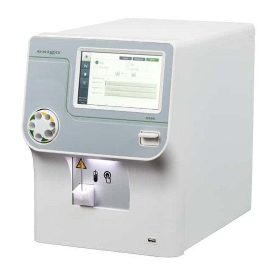
Page 6: Analyzer Overview
1. Introduction Analyzer Overview Analyzer Overview Figure 1: Analyzer front view Part Description/Function Display TFT-LCD Touch screen which displays patient and QC data, allows operator to enter setup and testing instructions, and prompts operator on next step. See section 7 for menu structure. Blood tube mixer Uniformly mixes samples before analysis. - Page 7 1. Introduction Analyzer Overview Figure 2: Analyzer cable and interface connections Part Description/Function USB host ports Connects analyzer to USB devices. USB device port Connects analyzer to USB host. Electronic sensors Connects Reagent level sensors to analyzer. Power supply port Connects Main power outlet to analyzer.
-
Page 8: Consumable Overview
1. Introduction Consumable Overview Consumable Overview Reagents Figure 4: Reagents Part Description/Function Diluent Isotonic diluting solution. Lyse Lytic solution. Cleaner Enzymatic Cleaner EOS Reagent QC Material Figure 5: QC Material Part Description/Function Boule Control QC material to verify analyzer operation. Boule Calibrator QC material to calibrate analyzer. -
Page 9: Reagent Consumption Specifications
Reagent Consumption Specifications Reagent Consumption Specifications Diluent Consumption: ≤ 25 mL per analysis cycle (with both EOS and non-EOS incubaton enabled). ≤ 55 mL per analysis cycle with Exigo EOS incubation enabled. Lyse Consumption: ≤ 5.2 mL per analysis cycle. - Page 10 1. Introduction Specifications Electrical Main Voltage 100–240 V Frequency 50–60 Hz Noise level ≤ 67 dB(A) Running: average 25W, peak 30W Maximum power consumptions Ready: 15W Standby: 10W Measuring principles MCV, MPV, RBC, WBC, and PLT Impedance Photometric Floating RBC/PLT discriminator Yes (position printed) Programmable WBC discriminator Mathematical 3-part diff.
-
Page 11: Performance
0.99 ≤ 1 Correlation Correlation is performed using a reference analyzer compared with the Exigo H400 system run in open tube mode with Dog profile. Carry-over Based on CLSI Standard H26-A2, using dog venous whole blood in open tube mode. -
Page 12: Safety Instructions
Intended Use The Exigo H400 system is an automated hematology analyzer for in vitro diagnostic use under laboratory conditions. The Exigo H400 is used for enumeration of white blood cells (WBC);... - Page 13 Handle any exposure according to established laboratory protocol regulations. The instructions for analyzer decontamination and disposal can be found on the Exigo home page, www.exigo-vet.com under Support.
- Page 14 1. Introduction Safety Instructions Signs on Equipment and Consumables Signs placed on the instrument define areas that need special attention or areas that contain danger. See figures 6 and 7. Batch code Serial number Catalogue number Manufacturer Authorized Representative Biological Risk Fragile, handle with care Use by in the European...
-
Page 15: Warranty Limitations
Operators and laboratory supervisors are responsible that Boule products are operated and maintained according to the procedures described in manuals and control inserts. Each Exigo H400 system is tested using recommended reagents, controls, calibrators and cleaners. All performance claims are generated as part of this complete system. -
Page 16: Section 2. Installation And Reagent Setup
2. Installation and Reagent Setup Unpack and Check Components SECTION 2. INSTALLATION AND REAGENT SETUP Unpack and Check Components Quick Reference Guide User Manual AC power adapter Power cord RFID reader MPA kit Reagent tube assemblies x 4 Waste tube Reagent bottle tray Service Part Figure 8: Analyzer packaging components... -
Page 17: Analyzer Placement And Environment
2. Installation and Reagent Setup Analyzer Placement and Environment Analyzer Placement and Environment The analyzer should be placed in a laboratory environment according to the guidelines below: Place the analyzer on a clean horizontal surface. Avoid direct exposure to sunlight. Make sure the analyzer has access to proper ventilation: 5 cm of free space above it and 10 cm of free space behind it. - Page 18 2. Installation and Reagent Setup Installation Checklist and Menu After completing the following eight Installation Menu steps, the system will be ready for the first sample analysis. X Installation Menu Set Language Choose language and press Save. Figure 10: Language menu Figure 9: Installation menu Set Time In this menu 4 different options are available:...
- Page 19 Option 1 (recommended): now complete. Select Startup Sequence. This sequence guides the operator through the beginning of the day startup routine for the To prepare the Exigo H400 to analyzer. analyze a sample perform one of the following: © Boule Medical AB, March 2018. Article no. 1504496...
- Page 20 The Exigo H400 system is interlocked with specified Boule reagents, Exigo Diluent, Exigo Lyse, Exigo Cleaner and Exigo EOS (hereafter referred to as Diluent, Lyse, Cleaner and EOS), for optimal performance. The reagent containers must be identified by the analyzer before analysis of samples can begin.
- Page 21 2. Installation and Reagent Setup Installation Checklist and Menu Lyse Lyse Diluent Cleaner Diluent Cleaner Figure 18: Reagent tubing installation 5 Insert each reagent tube assembly into the corresponding reagent container. Lyse Diluent Cleaner Figure 19: Reagent tubing installation X Waste Tube Installation Connect the waste tube to the analyzer.
- Page 22 2. Installation and Reagent Setup Installation Checklist and Menu Changing Reagents The interlocked reagent system displays indicator and warning messages to alert the operator when reagents are running low and need to be changed. When this occurs perform the following: X Changing Reagents 1 Select Quick Functions Menu and then select Add Reagent.
-
Page 23: Section 3. Operation (Sample Analysis)
3. Operation (Sample Analysis) Preparations before Analysis SECTION 3. OPERATION (SAMPLE ANALYSIS) Preparations before Analysis See section 4, “Sample Collection”. Startup Sequence The following sequence describes the daily startup routine for the analyzer including background and control analysis. The startup sequence is optional and must be activated to follow this procedure, alternatively follow the manual background and quality control checks. -
Page 24: Background Count
Analyze Control Control samples are analyzed to verify the performance of the Exigo H400 system. Follow the instructions on the screen: Either scan in barcode on control vial or choose the circle next to the desired lot number and level of control. -
Page 25: Analyzing Sample (Open Tube)
3. Operation (Sample Analysis) Analyzing Sample (Open Tube) 3 The aspiration time is approximately 10 seconds. After ~ 10 seconds the analyzer will time out due to no detection of blood, and continue its cycle. 4 The background count should not be higher than the values shown in figure 28: Rerun sample if values are not acceptable. - Page 26 3. Operation (Sample Analysis) Analyzing Sample (Open Tube) Choose Sample ID 1 and Sample IDs can be entered either manually or by barcode. Sample ID 2 Operator can enter up to 50 characters for each ID. The green indicator next to the fields shows which field the next barcode can be entered into.
-
Page 27: Analyzing Sample (Micro Pipette Adapter, Mpa)
3. Operation (Sample Analysis) Analyzing Sample (Micro Pipette Adapter, MPA) Analyzing Sample (Micro Pipette Adapter, MPA) The following steps will guide the operator through analyzing a whole blood sample with the use of the Micro Pipette Adapter (MPA). Note: EOS parameter is not available through MPA mode. ONLY Boule supplied, plastic, high precision EDTA micropipettes should be used when running MPA. - Page 28 3. Operation (Sample Analysis) Analyzing Sample (Micro Pipette Adapter, MPA) Note: Do not remove MPA device during sample aspiration or analysis. Removal prior to completion of analysis may cause erroneous results. Read section 4 on “Venous Blood Sample Collection” before commencing. X Analyze Venous Sample (Micro Pipette Adapter, MPA) Enter Sample Information Follow instructions 1–5 under “Analyzing Sample (Open...
-
Page 29: Results
3. Operation (Sample Analysis) Results Results After a sample has been analyzed the result information will be displayed on the screen. The operator can also search for previous sample analyses, look at statistics, and print and export them. X New Sample Analysis Results The Sample Result screen can be divided into four main sections. - Page 30 3. Operation (Sample Analysis) Results Section 3: Parameter Scales and Graphs Normal range display bars with sample results Green bar = Result within normal range − Red bar = Result Out-of-Range − Purple bar = Result outside of visible bar range −...
- Page 31 3. Operation (Sample Analysis) Results X Sample Result List and Search Function Figure 42: Result List Screen Figure 43: Search Screen Enter Result List Mode Go to Result List screen to view list of results. View Results To view a specific sample result from the list use the scroll arrows to scroll to sample and then press on field with desired sample result.
- Page 32 3. Operation (Sample Analysis) Results View Sample Statistics For a quick view of all sample statistics press Statistics button. In the Sample Statistics Menu the operator will be able to view: Parameter − Number of samples used in statistics − Mean value of selected samples −...
-
Page 33: Section 4. Sample Collection
4. Sample Collection Venous Blood Sample Collection SECTION 4. SAMPLE COLLECTION Venous Blood Sample Collection Venous blood samples should be collected in a K2EDTA or K3EDTA tubes in sufficient quantity and be gently mixed after sampling in order to obtain accurate results. Please follow the recommendation of the EDTA tube supplier. - Page 34 4. Sample Collection Handling of capillary blood samples X Capillary Blood Sample Collection and Analysis This section describes how to analyze capillary whole blood samples with the use of the Micro Pipette Adapter (MPA). Only Boule supplied, plastic, high precision EDTA micropipettes should be used when running MPA.
- Page 35 4. Sample Collection Handling of capillary blood samples Fill the micropipette completely with fresh whole blood and wipe off excessive blood on the outside surface. Be careful not to wick blood from open ends of the micropipette. Ignoring these instructions might cause incorrect and non-reproducible results. Complete procedure Transport sample to analyzer for processing by inserting filled micropipette into the MPA adapter using the...
-
Page 36: Section 5. Quality Control
SECTION 5. QUALITY CONTROL Analyzing Control Sample It is advisable that the performance of the Exigo H400 system is checked daily with a certified blood control authorized by Boule. Comparing the analyzer results to the known values on the Boule control assay sheet is a good assurance that the system is functioning properly. - Page 37 Analyze Control Control samples are analyzed to verify the performance of the Exigo H400 system. Follow the instructions below to analyze control. X Analyze Control Enter Control Analysis Mode Go to Start Menu.
- Page 38 5. Quality Control Analyzing Control Sample Figure 52: Select Control Figure 53: Control Results Enter barcode Either scan in barcode on control vial or choose the circle next to the desired lot number of control. Analyze Control Press Start Plate, analyzer will now analyze the control sample.
-
Page 39: Quality Assurance Functions
The Exigo H400 system includes numerous Quality Assurance functions to ensure that the analyzer and reagents are working properly and that the operator procedures are performed correctly. The Exigo H400 system has been designed and manufactured according to Boule Medical ISO 13485 quality system procedures. - Page 40 5. Quality Control Quality Assurance Functions Control and Calibrator Search Function The operator can search for previous control and calibrator analyses, view statistics, and print/send QC samples and summary reports. X QC Results and Search Function Enter QC Search Mode Go to Main Menu and select Quality Control Menu.
- Page 41 5. Quality Control Quality Assurance Functions Print/Send Results To print a specific QC sample result, select Print. To Send a specific QC sample result, select Export. For a quick view of all sample statistics press Statistics View QC Statistics button. In the Sample Statistics Menu the operator will be able to view: Parameter...
- Page 42 5. Quality Control Quality Assurance Functions X Levey-Jennings Plots Figure 59: QC Menu Figure 60: L-J Plot Results Enter QC Mode Go to Main Menu and then select Quality Control Menu. Select Control L-J. Enter Levey-Jennings Mode L-J Plot Results Samples during the latest 90 days are shown as a default for the L-J plots.
-
Page 43: Section 6. Calibration
6. Calibration Calibration SECTION 6. CALIBRATION Calibration The analyzer has been calibrated by Boule prior to shipment. Good laboratory practice, however, requires regular checks and calibration of the measured parameters. Only authorized operators can update or change calibration factors. See Chapter 7 for User Login and Advanced User. Calibrator Handling Recommendations Handle and prepare calibrator in accordance to calibrator package insert. - Page 44 6. Calibration Calibration X Guided Calibration The Guided Calibration is a step-by-step assisted calibration, usable for both Open Tube and MPA inlets and always requires 5 Boule Calibrator runs. Note: It is possible to exit the Guided Calibration at any time, and already analysed samples can be used in Advanced Calibration.
- Page 45 6. Calibration Calibration Continuation of Calibrator Repeat steps 2 to 4 above until all 5/5 samples have been Analysis analysed. Figure 64: Consecutive Guided Calibration Analysis When pressing button Accept Analysis for sample 5/5 a Completion of Guided Calibration calibration result screen is displayed showing results for all parameters together with a pass/fail status column.
- Page 46 X Advanced Calibration Select Calibration Procedure Calibration of the analyzer can be performed in three different ways: Method 1: The recommended method is to use Boule calibrator which will automatically calculate the new calibration factor using target values from assay values. Method 2: If no calibrator is available, use a sample with known values or determine target values using a reference analyzer or microscope method with an...
- Page 47 Calibration Go to Main Menu and login using Authorization Code 5075. Select Calibration and then Whole Blood, Advanced Calibration. Analyses will be displayed, along with the following for each parameter: Assay Value − − Measured Value Figure 67: Calibration Results −...
- Page 48 Calibration Log in as in Method 1, enter Calibration and then Whole Blood but then select Factors. Enter target values under the heading Target. Once all target values have been entered, press Accept and the analyzer will calculate and display the new factors.
-
Page 49: Section 7. Menu Structure And Advanced Setup
7. Menu Structure and Advanced Setup Menu Structure SECTION 7. MENU STRUCTURE AND ADVANCED SETUP Menu Structure Display screens may vary pending on user login level. Advanced User menus highlighted in gray. = Start Menu − Keyboard Entry Screen = Result List −... - Page 50 7. Menu Structure and Advanced Setup Menu Structure Main Menu Flowchart Setup Menu Maintenance Menu 1 Quality Control Menu Main Menu Maintenance Menu 2 (Cleaning) Menus with Advanced User login Calibration Menu Instrument Info Menu Calibration Menu Setup Menu 2 (Advanced Setup) Service Info Menu Figure 73: Main Menu Flowchart Page 50...
- Page 51 7. Menu Structure and Advanced Setup Menu Structure Setup Flowchart Waste Counter Setup Printer Setup Setup Menu Touch Screen Test Menus with Advanced User login Communication Setup Screen-saver Setup Date and Time Setup Advanced Setup Menu Profile Setup Regional Setup Parameter Setup Menu Sampe Storage Reagents...
- Page 52 7. Menu Structure and Advanced Setup Menu Structure Advanced Setup Flowchart Menus with Advanced User login Barcode Setup Blood Detector Setup Advanced Setup Menu Instrument ID Setup High Altitude Setup Touch Screen Calibration PLT Setup Sample ID 2 Setup Quick Functions Administrate Users Mixer Setup Standby Setup...
-
Page 53: Advanced Parameter Setup
7. Menu Structure and Advanced Setup Advanced Parameter Setup Advanced Parameter Setup Initial advanced setup of the analyzer has been factory set to default values. However, other operator definable formats may be preferred. Details on how to install and configure these parameter are provided in this section. - Page 54 7. Menu Structure and Advanced Setup Advanced Parameter Setup When using a printer that is PostScript compatible, − select PostScript Compatible. If using a printer other than that specified by distributor, − the printer must be HP PCL 3 and 5, Proprinter/Epson or PostScript compatible.
- Page 55 7. Menu Structure and Advanced Setup Advanced Parameter Setup One Ticket Per Page This function allows the user to print more than one analysis per page. Select One Ticket Per Page, select Enabled to print one analysis per page or Disabled to print more than one analysis per page, press Accept, and then Save.
- Page 56 7. Menu Structure and Advanced Setup Advanced Parameter Setup Parameter and Histogram order for custom ticket format This function allows the user to choose the order of the parameters and histograms on the printouts. Firstly make sure the Printer Setup, Ticket Format is set to Customized.
- Page 57 7. Menu Structure and Advanced Setup Advanced Parameter Setup Export Target This function allows the user to choose how and where data is exported. USB Storage (XML) – To activate the export of data to a USB memory stick, choose USB Storage (XML) button, then Enabled, and then press Save.
- Page 58 7. Menu Structure and Advanced Setup Advanced Parameter Setup Export Setup General settings for export of data can be found here. Manual Export Mode – Setup the manual export mode of samples by either selecting Without histograms or With histograms, and then press Save. Auto Export Mode –...
- Page 59 7. Menu Structure and Advanced Setup Advanced Parameter Setup Excel Setup This function allows the user to define what to use as a decimal symbol in a csv file. The Decimal Symbol can be set to either .(Period) or ,(Comma). Figure 96: Excel Setup Network Identification Check with Technical Support for more information.
- Page 60 7. Menu Structure and Advanced Setup Advanced Parameter Setup X Language Figure 98: Language Setup This function allows the language be changed to operator preference. Choose Regional and then Language. Choose language and press Save. X Waste Counter Setup In this setup menu the user can choose preferences for utilization of a waste container and the associated preferences: waste container volume, warning level, and counter reset.
- Page 61 7. Menu Structure and Advanced Setup Advanced Parameter Setup X Sequence Number Setup To reset the sequence number, enter Sample Storage, choose desired sequence number, and then press to save. X Set Default Profiles During routine daily operation often the same patient type or patient profile is analyzed. The operator has the option to select a default profile.
- Page 62 Accept and then Save to save the new settings. X Analysis Profile Setup Analysis profiles have been predefined in the Exigo H400 analyzer. Each analysis profile has many different formatting options, including profile name, default settings, normal ranges, analysis constants, blocking parameters, etc. To add or change analysis profile settings follow these step by step instructions below.
- Page 63 7. Menu Structure and Advanced Setup Advanced Parameter Setup Normal Range Setup Indicative ranges are provided in this instrument. It is recommended to establish local reference ranges (normal ranges) for the profiles used in your laboratory. See CLSI standard EP28-A3C for guidance on how to establish these ranges.
- Page 64 7. Menu Structure and Advanced Setup Advanced Parameter Setup When all desired parameters have been setup press Save on Profile Settings menu to save new profile. X Advanced Setup Blood Detector Setup This function allows the operator to enable and disable the blood detector for each aspiration type.
- Page 65 7. Menu Structure and Advanced Setup Advanced Parameter Setup PLT Setup The function of the PLT offset is to set a background count for PLT. It is recommended to keep PLT offset value at 0. (This function should not be used for the purpose of forcing QC background count acceptance.) PLT Offset Setup To change the default press PLT Offset button.
- Page 66 7. Menu Structure and Advanced Setup Advanced Parameter Setup Minutes before Standby To change the default press Standby Timeout button. It can be set from 10 to 240 minutes. Press to accept the new values and then Save. Sequence after Standby When activated this function will either perform an automatic background count or the Startup sequence when the analyzer comes out of Standby.
- Page 67 7. Menu Structure and Advanced Setup Advanced Parameter Setup Parameter Order Change Parameter Order 1. Click tab Parameter and select desired parameter to change the order for. 2. Press the up/down arrow until selected parameter is in the desired position. 3.
- Page 68 7. Menu Structure and Advanced Setup Advanced Parameter Setup Change profile order Note that profiles that are inactivated (see In-activated profiles Step 2 above), will not be visible in the Edit Profile Order list. 1. Click button Edit Order. 2. Click on the profile you want to change position of. 3.
- Page 69 7. Menu Structure and Advanced Setup Advanced Parameter Setup Removing of a Functional Button 1. Click button for removal. 2. Click button Remove. 3. Press button Save to store new quick menu. Change function of a Functional Button 1. Click button for editing and press Edit. 2.
- Page 70 7. Menu Structure and Advanced Setup Advanced Parameter Setup User Login The instrument allows for two modes of login. Level Login (default), where each level have an unique password and allows for an increasing set of available settings and functions or User Login, where a set of personal users are created and each user is assigned a level with its associated set of available settings and functions.
- Page 71 7. Menu Structure and Advanced Setup Advanced Parameter Setup Log in with User Login 1. Select which user to log in from User Login list. 2. Input password and press OK button. Figure 114: User Login Add User 1. Login as Admin and go to Setup > Page 2 > Administrate Users.
- Page 72 7. Menu Structure and Advanced Setup Advanced Parameter Setup Service Log This function is used to export instrument data useful for Service. Export service log, standard usage: From System Info > Page 2: 1. Insert USB memory into instrument. 2. Press button Export Service Log. Page 72 ©...
-
Page 73: Section 8. Technology
Measuring Principles SECTION 8. TECHNOLOGY Measuring Principles The measuring principles of the Exigo H400 analyzer are based on impedance and spectrophotometer principles. Whole Blood Dilution The RBC and WBC concentration values are determined by counting cells in whole blood dilutions of 1:40,000 for the RBC and 1:400 for the WBC and EOS. -
Page 74: Wbc Differentials
WBC Differentials Floating Discriminator Technology The Exigo H400 system uses a floating discriminator technology to estimate the best separation between 3 populations of white blood cells (lymphocytes, granulocytes and mono-cell fractions). After the analyzing process, the analyzer finds two main modes (Granulocyte Peak and Lymphocyte Peak) within the total distribution. -
Page 75: Measurement Of Eosinophils
8. Technology Measurement of Eosinophils Measurement of Eosinophils 4 part WBC differential impedance based analyzer • The method is included the conventional 3 part differential analysis together with an added EOS measurement with a total analyzing time of about 3 minutes. •... -
Page 76: Section 9. Troubleshooting And System Messages
9. Troubleshooting and System Messages Troubleshooting SECTION 9. TROUBLESHOOTING AND SYSTEM MESSAGES Troubleshooting General Information Displays General information displays are informative screen displays that appear after a function has been completed. Instruction is then displayed for the operator on next step or function to be performed. Warning Displays Warning displays appear after a function has been performed incorrectly or to inform the operator that further action is needed to complete the desired task. - Page 77 9. Troubleshooting and System Messages Troubleshooting Communication Issues This section contains information regarding errors associated with printers. Issue Solution Cause The printout has unusual Verify that printer type matches the printer New printer was connected but being used. not matched with analyzer setup. layout or strange characters.
-
Page 78: System Information Messages
9. Troubleshooting and System Messages System Information Messages System Information Messages As samples are analyzed, the system software may produce two types of intelligent information messages. The information is designed to guide and aid the user in the practice of complete hematology. -
Page 79: Sample Pathology Messages And Flag Indicators
9. Troubleshooting and System Messages Sample Pathology Messages and Flag Indicators of their cytoplasmic membranes compared to normal cells, which may cause aberrations in the automated analysis. This also applies to the presence of normal non-pathological cells that have been subjected to chemotherapy or other treatments. - Page 80 9. Troubleshooting and System Messages Sample Pathology Messages and Flag Indicators Distribution Indicators (RBC, PLT, WBC) Indicator Message Description Action Small particle interference The size distribution of the cell pulses departs Blood sample too from the expected one. Possible reasons might old or pathological be pathological blood sample (e.g.
- Page 81 9. Troubleshooting and System Messages Sample Pathology Messages and Flag Indicators Measuring Chamber Indicators (RBC, PLT, WBC) Indicator Message Description Action Measurement warning The cell pulses arrived faster than the analyzer Re-analyze sample. could process them. Possible reasons might be air bubbles, electrical disturbances or incomplete lysing.
- Page 82 9. Troubleshooting and System Messages Sample Pathology Messages and Flag Indicators Lyse system problem The analyzer detected an abnormality during the fill cycle of the lyse pipette. Reasons for flagging might be timeout, short time or bubbles at the Verify analyzer is upper detector.
- Page 83 9. Troubleshooting and System Messages Sample Pathology Messages and Flag Indicators X Sample Pathological Information Messages WBC Differential (LYM, MON, GRA/NEU, EOS) Indicator/Message Criteria Description Action Pathological If total WBC is > WBC: Leukocytosis; slide review adviced Message 15% above upper limit.
- Page 84 9. Troubleshooting and System Messages Sample Pathology Messages and Flag Indicators Indicator/Message Criteria Description Action Pathological If HCT is > 10% HCT: Anemia; evaluate RBC on slide Blood sample too old Message below lower limit or pathological sample. Re-analyze sample, if Pathological If HCT is >...
-
Page 85: Section 10. Analyzer Care And Maintenance
Dry carefully. Automatic Cleaning The Exigo system has been designed to clean internal components on a daily basis. The system uses the enzymatic cleaner to flush and clean all components that come into contact with blood when in standby or power-off mode. -
Page 86: Transport (Short-Term And Long-Term)
10. Analyzer Care and Maintenance Transport (Short-term and Long-term) Figure 120: Maintenance Menu Figure 121: Cleaning Menu Clot Removal Check with your local Service Contact for more information. Annual Cleaning Boule Cleaning Kit Procedure To increase the life of the analyzer’s internal tubing, the following cleaning procedure is strongly recommended. - Page 87 Power on analyzer. Perform Prime. Verify Background. It is recommended that the performance of the Exigo H400 system is checked with certified blood controls authorized by Boule. Short–Term Shutdown (< 12h) This section describes the procedure performed before transporting the analyzer over short distances outside the usual facility.
- Page 88 10. Analyzer Care and Maintenance Transport (Short-term and Long-term) The main difference between Relocation/Short-Term Shutdown and Long-Term Shutdown is the importance of cleaning the instrument with the Boule Cleaning Kit and distilled water, prior to repackaging to avoid contaminates. X Repackaging, Long-Term Transport and Storage 1 Select Main Menu, then Maintenance, and arrow over to next page to enter the Cleaning Menu.
-
Page 89: Maintenance/Service
The European Directive 2012/19/EU on Waste Electric and Electronic Equipment (WEEE) aims to minimize the impact on the environment by prevention of waste. The Exigo H400 hematology analyzer has been labeled with the WEEE symbol, and there is a procedure to allow waste collection and recycling of the equipment at the end of it’s life cycle. - Page 90 10. Analyzer Care and Maintenance Disposal Information Page 90 © Boule Medical AB, March 2018. Article no. 1504496...
-
Page 91: Appendix
Appendix APPENDIX Appendix A: Parameter Definitions Parameters presented in alphabetical order. All measured parameters except HGB are based on the principle of impedance. HGB measurements are based on photometry. The expression of very low values of some parameters has been limited due to low statistical significance. The limits are given as information. - Page 92 Appendix PLT (Platelets) The number of cells for determining PLT values are counted from a dilution of whole blood. PLT and MPV are however blocked for Goat and New World Camel profiles. RBC (Red Blood Cell) The number of cells for determining RBC values are counted from a dilution of whole blood. RDW (Red Cell Distribution Width) The RDW parameters, both relative (RDW%) and absolute (RDWa) are calculated from the RBC size distribution curve and are only presented if the MCV value is displayed.
- Page 93 Appendix Appendix B: Third-Party Software Appendix B: Third-Party Software This product uses some software which are distributed under the GPL and/or the LGPL licences. Accordingly, Boule Medical AB makes the source code (including changes made by Boule Medical AB) for the following GPL and/or LGPL licensed software available: U-boot, Linux Kernel, Busybox, Glibc, Glib, GTK.
-
Page 94: Index
11. Index INDEX Index Advanced Parameter Setup ....53 Fill ....... 19, 21, 28, 35 Advanced Setup Menus . - Page 95 11. Index System Info ....... . . 17 System Information Messages ... . 39, 78, 79 New Sample .
- Page 96 Page 96 © Boule Medical AB, March 2018. Article no. 1504496...
- Page 97 Produced by Boule Medical AB Domnarvsgatan 4, SE-163 53 Spånga, Sweden © Boule Medical AB, March 2018. Article no. 1504496...
Need help?
Do you have a question about the H400 and is the answer not in the manual?
Questions and answers