Advertisement
DKG-175 User Manual
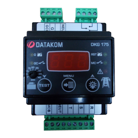
DESCRIPTION
Datakom DKG-175 is a DIN Rail mounted ATS
controller not requiring DC supply. Thanks to this
feature, it is not required to carry the DC supply from
the battery to the transfer panels, providing ease of
installation.
The unit monitors 3-phase mains voltages, sends
remote start command to the generating set and
performs changeover of both generator and mains
contactors.
The front panel leds provide information about mains
and generator power availability as well as contactor
positions. Moreover, mains phase voltages and
frequency can be seen on front panel.
Mains voltage and frequency high and low limits,
mains waiting timer, mains fail timer, generator start
delay, cooldown timer and mains contactor timer are
front panel programmable. Generator contactor timer
is adjustable between 1 and 40 seconds through front
panel knob.
DKG-175 AUTOMATIC
TRANSFER SWITCH
(WITHOUT DC SUPPLY)
DIN Rail mounted
No DC supply required
Mains phase order check
Adjustable MCB and GCB delays
Programmable mains frequency and voltage high
and low limits
Programmable delay timers
10A/250VAC MCB and GCB outputs
10A/28VDC remote start output
Isolated mains and genset inputs
Test mode
V-1
(24.07.2017)
FEATURES
Advertisement
Table of Contents

Subscribe to Our Youtube Channel
Related Manuals for Datakom DKG-175

Summary of Contents for Datakom DKG-175
- Page 1 (WITHOUT DC SUPPLY) DESCRIPTION FEATURES DIN Rail mounted Datakom DKG-175 is a DIN Rail mounted ATS controller not requiring DC supply. Thanks to this No DC supply required feature, it is not required to carry the DC supply from Mains phase order check...
- Page 2 DKG-175 User Manual (24.07.2017) SAFETY NOTICE Failure to follow below instructions will result in death or serious injury Electrical equipment should be installed only by qualified specialist. No responsibility is assured by the manufacturer or any of its subsidiaries for any consequences resulting from the non-compliance to these instructions.
-
Page 3: Table Of Contents
DKG-175 User Manual (24.07.2017) TABLE OF CONTENTS Section 1. INSTALLATION INSTRUCTIONS 1.1. Front Panel 1.2. Electrical Connections 2. LED INDICATORS 3. PUSHBUTTON FUNCTIONS 4. OPERATION OF THE UNIT 4.1. Test Mode 5. PROGRAMMING 6. DECLARATION OF CONFORMITY 7. TECHNICAL SPECIFICATIONS 8. -
Page 4: Installation Instructions
DKG-175 User Manual (24.07.2017) 1. INSTALLATION INSTRUCTIONS Before installation: Read the user manual carefully, determine the correct connection diagram. Be sure that the temperature of the environment will not exceed the maximum operating temperature in any case. Below conditions may damage the device: ... -
Page 5: Front Panel
DKG-175 User Manual (24.07.2017) 1.1 Front Panel - 5 -... -
Page 6: Electrical Connections
DKG-175 User Manual (24.07.2017) 1.2 Electrical Connections Do not install the unit close to high electromagnetic noise emitting devices like contactors, high current busbars, switch mode power supplies and the like. Although the unit is protected against electromagnetic disturbance, excessive disturbance can affect the operation, measurement precision and data communication quality. -
Page 7: Led Indicators
DKG-175 User Manual (24.07.2017) 2. LED INDICATORS Indicator Colour Description Yellow Generator voltage is within limits. Yellow Generator contactor is energised. Green Mains voltage and frequency is inside within limits. Shows that mains waiting timer is counting if it is blinking. -
Page 8: Operation Of The Unit
DKG-175 User Manual (24.07.2017) 4. OPERATION OF THE UNIT If 3-phases of mains voltage and frequency are withing limits and phase order is correct: -MC, RST leds turn on. -MCB terminal is supplied with voltage R. -REMOTE START relay will be energised. (Normally closed and normally open contacts will switch position.) -
Page 9: Programming
DKG-175 User Manual (24.07.2017) 5. PROGRAMMING DKG-175 has programmable parameters to provide flexibility to the user. Press and hold buttons for 5 seconds to enable programming mode. Click buttons to navigate between parameters when device displays program number. Click button to display value of the program parameter. -
Page 10: Declaration Of Conformity
DKG-175 User Manual (24.07.2017) Mains fail timer Mains contactor will be off after the delay adjusted with program parameter P9. Mains fail timer starts counting when mains is off. Phase order check 0: Mains phase order check disabled 1: Mains phase order check enabled Test mode timer Test mode will be deactive at the end of timer adjusted with program parameter P10. -
Page 11: Connection Diagram
DKG-175 User Manual (24.07.2017) 8. CONNECTION DIAGRAM DATAKOM Electronics Ltd. Tel: +90-216-466 84 60 Fax: +90-216-364 65 65 e-mail: datakom@datakom.com.tr http: www.datakom.com.tr - 11 -...
Need help?
Do you have a question about the DKG-175 and is the answer not in the manual?
Questions and answers