
Summary of Contents for FaceID F910
- Page 1 F910 Facial Recognition Terminal User Manual ...
- Page 2 In no event shall Hanvon be liable for any loss or damage caused by the use of this manual. This manual describes F910 facial recognition terminal in detail and contains full operating instructions.
-
Page 3: Table Of Contents
Content 1. About this document ............4 2. Product Features.............. 5 2.1 Appearance View ............... 5 2.2 Installation Guide ............... 6 2.3 Connection Port ..............7 2.4 Power up terminal .............. 8 3. Operating Guide ............... 9 3.1 Admin. Management ............9 3.2 User Management............ -
Page 4: About This Document
These instructions are valid for the F910 Facial Recognition Terminal. Target group The target group for this document comprises the terminal operator and technical personnel. Content and purpose These user manual describe the F910 facial recognition terminal installation and operation information to users. Supplementary documents Abbreviations Hanvon Hanwang Technology Co., Ltd Brand... -
Page 5: Product Features
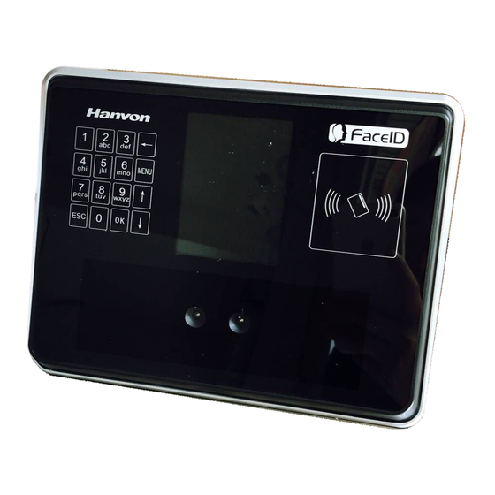
1. Product Features 2.1 Appearance View RFID Reader Display Button: Previous or next field Button: Main function menu Button: Backspace and delete Button: Digital Keypad Button: Cancel button Button: Confirm button Camera Loudspeaker Reset Button USB Socket Power Adaptor Port Network Cable Port Connection Port Confidential... -
Page 6: Installation Guide
2.2 Installation Guide User can drill the holes according to the mounting diagram. Use the 4 wall mount, screws to mount the bracket to the wall. User also could mount the terminal by choosing your “shortest” users and have them stand in front of the device. Hold the terminal on the wall that employee can comfortably center their face in the LCD display window. -
Page 7: Connection Port
2.3 Connection Port Definition Feature J1.1 VC12V 12V Power Supply J1.2 Ground J1.3 LOCK_NO Door Lock J1.4 LOCK_COM J1.5 LOCK_NC J1.6 DOORSENSOR Door Magnetic Detection J1.7 Ground J1.8 DOORSWITCH Door Switch J1.9 COM 2 Alarm/Bell Output J1.10 NO 2 Definition Feature J2.1 WGD0_IN... -
Page 8: Power Up Terminal
2.4 Power up terminal Select a proper language when the terminal boot first time. The terminal will provide several language options for customers: English Spainish Portuguese Turkish ┉┉ Confidential Page 8 ... -
Page 9: Operating Guide
2. Operating Guide 3.1 Admin. Management Admin. Management Main Menu If no admin. in system, then press <MENU> to enter the main menu. If there has enrolled admin. in system, then press <MENU> to enter admin. verifying process. While the verification is correct, then the system enter to the main menu. - Page 10 Admin. Types Super Admin. can operate all functions and normal administrators. The first administrator must be super admin and can’t be deleted in system. Normal Admin. operate User/Data/USB Management function, check system info. and auto test function. ...
- Page 11 User Photo: Press [OK] to capture a photo for the user. If don’t, please check [ESC]. Admin Verification After set an admin. account, then press <MENU> to activate admin verification process. Input admin. ID (or using registered RFID card) ...
-
Page 12: User Management
3.2 User Management User Management Main Menu User Enroll Input User ID The range of User ID is from 1-99,999,999,999,999. Input name Press to <MENU> will switch character inputing mode between <Upper Case> <Lower Case> and <Digital>. User Name can contain 18-bit characters totally. - Page 13 Select a privilege Access & Attendance: The terminal is used for access control and time attendance with relay output. Attendance: The terminal is only used for time attendance without relay output. User Photo: Press [OK] to capture a photo for the user. If don’t, please check [ESC].
- Page 14 Delete All Users Press [OK] (or [ESC]) to confirm (or cancel) this process. All user’s ID, name and templates will be erased. This step is irreversible. Not affect Admin data and records. User List Enter user list to check Un-enrolled and Enrolled list. ...
-
Page 15: Data Management
3. 3 Data Management Data Management Main Menu Record Management Record Inquiry: User records can be inquiry by User ID/Name. Select a search mode to inquiry user records. Select inquiry duration: 1 day/6 days /All records / from start date to end. - Page 16 Del. by Date: Input the delete time. Delete All Records All records will be erased. This step is irreversible. Backup all user data before doing this step. Security Photo Security Photo Switch: Turn on / off security photos function. Default switch is off.
-
Page 17: Usb Management
3.4 USB Management USB Management Main Menu Don’t remove USB Disk while data transferring. Try other USB Disk, if the terminal doesn’t recognize it. Export Management Exp. Admin.: Export all admin. data into a file which named as “MANAGER.TXT ”... - Page 18 Exp. Admin. Log: Export all admin operating logs. Data is stored into a “LOG.TXT” file. Exp. Security photos: Set a time duration of exporting security photos Security photos are saved in <security> folder Exp. Config. File: Export terminal configuration file into a file, which named as “sys.dat”.
- Page 19 PCM, 16000Hz, 16bit, stereo wave file, and named to <granted.wav> and <deny.wav> Keep audio length less than 1 second. Firmware Upgrade Upgrade a new firmware for a terminal. Firmware files are <F910.BIN> and <F910.TXT> Confidential Page 19 ...
-
Page 20: System Settings
3.5 System Settings System Main Menu Basic Date and Time Date and Time: System date and time can be set with this function. Date Format: System date format can be set in 9 formats. ... - Page 21 Volume Set Volume: terminal support 4 modes to customers. The default is medium. Head Photo Switch Photo ID Switch Switch On: Users head photo will display on the screen when the user verified successful. Switch Off: Users head photo will not display on the screen when user verified successful.
- Page 22 Network -Password It is for enhancing the security of network access through software or SDK. The password can be set max 8 bits. Network -Push to sever Push to sever Switch: On/OFF The default is off.
- Page 23 default CMD/HBP port 9920/9924. The default HBP Delay is 60. The port parameters have to more than 1024. The HBP delay range is 10~300. Communication -Wiegand Output Wiegand Output-Type: System supports standard Wiegand protocol output on the follow list. The default type is Wiegand output 26.
- Page 24 Attendance -Interval Interval: Only the first record will be saved while several records created by the same user during defined interval time. The default Interval is 1 minute. The interval range is 0~255 minutes. Attendance – Bell ...
- Page 25 Work Status: It is defined to mark the work status related to each record such as in, out, overtime in, overtime out. The default is off. If Work Status is on, user could select the desired work status by pressing down key<↑/↓>...
- Page 26 Attendance – Work Code Work Code: It is defined to mark the work code related to each record such as engineering, maintaining, training etc. The default is off. If Work Code is on, user has to select the desired work code after verification.
- Page 27 Unlock Sync: It is defined to enable the unlock execution synchronic to the attendance interval. The unlock execution will be only executed at the first time for the same user during defined time of attendance interval time. The default is off. ...
- Page 28 The default is OFF. Rejection Times: Set the rejection times to activate rejection alarm The default duration is 3 times. The rejection time range is 1~9 times. Advanced Relay 2 Output: User can set output to external Bell or Alarm output. ...
- Page 29 Algorithm Version: User can select V2.6 or V3.1 algorithm for a certain terminal. The default version is V3.1. The system will erase all enrolled users’ templates if change the algorithm version. Default: This operation will delete all data and configurations. And then initialize the device to factory setting.
-
Page 30: System Info
3.6 System Info. Capacity Info. Face: Current enrolled user numbers and total capacity of user numbers for face related recognition mode. Other: Current enrolled user numbers and total capacity of user numbers for card and ID+PIN related recognition mode. ... -
Page 31: Auto Test
3. 7 Auto Test Test All: Test all below hardware automatically Press <OK> if it is working normal Press <ESC> if it is working abnormal. A list of status will be displayed after all testing. Check LCD: Display Red, Green and Blue on the screen ... - Page 32 Check Camera. Check RFID Cards. Check Network. Check USB Disk. Confidential Page 32 ...
-
Page 33: Appendix
3. Appendix Appendix1. Product Specification User capacity 2,000 users for face related verification method; 10,000 users for other verification methods including card, card and photo, ID and Pin Record capacity Data Capacity:200,000 Security Photo: 200,000 Verification methods Face Card and Face Card or Face... -
Page 34: Appendix2. Caution
Appendix2. Caution Installation Environment Terminal should install inside of the room, and make sure the installation place far with the window/door/light more than 2 meters. Outside of the room Sunlight directly shines on the Sunlight slanted shines on the terminal through the window. - Page 35 Please prevent the screen from oil or any sharp objects. Please use the equipped adapter terminal, other unknown adapters will burn out th t Warning Any Changes or modifications not expressly approved by the party responsible for compliance could void the user’s authority to operate the equipment. This device complies with part 15 of the FCC Rules.
- Page 36 —Consult the dealer or an experienced radio/TV technician for help. This equipment complies with FCC radiation exposure limits set forth for an uncontrolled environment. This equipment should be installed and operated with minimum distance 20cm between the radiator& your body. Confidential Page 36 ...
Need help?
Do you have a question about the F910 and is the answer not in the manual?
Questions and answers