Table of Contents
Advertisement
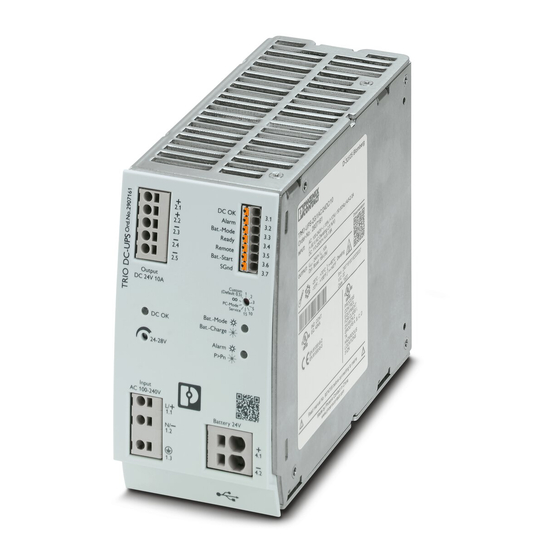
TRIO-UPS-2G/1AC/24DC/10
Uninterruptible power supply
Data sheet
107432_en_02
1
Description
The TRIO-UPS-2G uninterruptible power supply (UPS) with
integrated power supply unit is used to ensure that secure
DC power for critical electrical loads continues to be
supplied in the event of disturbances in the power supply
network, e.g. due to mains breakdown or failure. In the event
of such a disturbance, the UPS switches to battery
operation without interruption so that connected loads
continue to be continuously supplied. In this operating
mode, the output voltage is directly dependent on the
battery voltage. When mains power is restored, the UPS
automatically returns to normal operation. The connected
loads are again supplied via the power supply network and
the battery is charged at the same time. The TRIO-UPS-2G
uninterruptible power supply (UPS) is designed specifically
for supplying industrial PCs (IPCs).
Features
–
Power supply, loading unit and electronic switchover
unit in a device
–
Wide-range input AC
–
Adjustable output voltage in mains operation
–
USB interface for configuration and diagnostics
–
Adjustable charging parameters for the use of different
types of energy storage
–
Comprehensive signaling
Make sure you always use the latest documentation.
It can be downloaded from the product at phoenixcontact.net/products.
© PHOENIX CONTACT
2018-04-19
Technical data (short form)
Input voltage range
Nominal output voltage (U
Nominal output current (I
Buffer period
Residual ripple
MTBF (IEC 61709, SN 29500)
Maximum power dissipation in no-
load condition
Power loss nominal load max.
Ambient temperature (operation)
Ambient temperature (start-up type
tested)
Dimensions W/H/D
Weight
100 V AC ... 240 V AC
110 V DC ... 250 V DC
)
24 V DC
N
)
10 A
N
to 3 h
< 20 mV
> 2007013 h (230 V AC, at 25 °C)
> 1210518 h (230 V AC, at 40 °C)
> 575978 h (230 V AC, at 60 °C)
< 3 W (for 230 V AC)
< 32 W (for 230 V AC)
-25 °C ... 70 °C ( > 60 °C Derating:
2.5 %/K )
-40 °C
68 mm / 130 mm / 160 mm
1.34 kg
Advertisement
Table of Contents

Related Manuals for Phoenix Contact TRIO-UPS-2G/1AC/24DC/10


Summary of Contents for Phoenix Contact TRIO-UPS-2G/1AC/24DC/10
-
Page 1: Description
TRIO-UPS-2G/1AC/24DC/10 Uninterruptible power supply Data sheet 107432_en_02 © PHOENIX CONTACT 2018-04-19 Description The TRIO-UPS-2G uninterruptible power supply (UPS) with integrated power supply unit is used to ensure that secure Technical data (short form) DC power for critical electrical loads continues to be Input voltage range 100 V AC ... -
Page 2: Table Of Contents
Safety and installation notes ....................10 Structure..........................12 Mounting and removing ......................14 Device connection ......................... 16 Device operation ........................20 Method of operation....................... 25 Battery management ......................25 Signaling..........................26 Interface ..........................29 Derating..........................29 Parallel operation........................30 107432_en_02 PHOENIX CONTACT 2 / 30... -
Page 3: Ordering Data
DC, 38 Ah, automatic detection, and communication with QUINT UPS-IQ Used for communication between an industrial PC and MINI-SCREW-USB- 2908217 Phoenix Contact devices with USB-Mini-B connection. DATACABLE 2-piece universal wall adapter for securely mounting the UWA 130 2901664 power supply in the event of strong vibrations. The profiles that are screwed onto the side of the power supply are screwed directly onto the mounting surface. -
Page 4: Technical Data
Output connection data Connection method Push-in connection Conductor cross section, solid 0.2 mm² ... 4 mm² Conductor cross section, flexible 0.2 mm² ... 2.5 mm² Conductor cross section AWG/kcmil 24 ... 12 Stripping length 10 mm 107432_en_02 PHOENIX CONTACT 4 / 30... - Page 5 24 V DC Continuous load current 20 mA Status display LED ( yellow ) Status and diagnostic indicators/signal outputs Ready Switching output Transistor output, active Output voltage 24 V DC Continuous load current 20 mA 107432_en_02 PHOENIX CONTACT 5 / 30...
- Page 6 > 2007013 h (230 V AC, at 25 °C) Degree of protection IP20 Protection class Side element version Aluminum Hood version Dimensions W/H/D (normal mounting position/delivered 68 mm / 130 mm / 160 mm condition) Weight 1.34 kg 107432_en_02 PHOENIX CONTACT 6 / 30...
- Page 7 DIN VDE 0100-410 Approvals UL approvals UL Listed UL 61010 UL/C-UL Listed ANSI/ISA-12.12.01 Class I, Division 2, Groups A, B, C Current approvals/permissions for the product can be found in the download area under phoenixcontact.net/products 107432_en_02 PHOENIX CONTACT 7 / 30...
- Page 8 2 kV (Test Level 3 - asymmetrical) asymmetrical) Signal 0.5 kV (Test Level 2 - 1 kV (Test Level 2 - asymmetrical) asymmetrical) Comments Criterion B Criterion A Conducted interference EN 61000-4-6 Input/Output/Signal asymmetrical asymmetrical 107432_en_02 PHOENIX CONTACT 8 / 30...
- Page 9 Temporary impairment to operational behavior that is corrected by the device itself. All technical specifications are nominal and refer to a room temperature of 25 °C and 70% relative humidity at 2000 m above sea level. 107432_en_02 PHOENIX CONTACT 9 / 30...
-
Page 10: Safety And Installation Notes
This symbol and the accompanying text provide the reader with additional information or refer to detailed sources of information. 107432_en_02 PHOENIX CONTACT 10 / 30... - Page 11 SELV. These may only be operated on permitted SELV circuits. – Keep these instructions in a safe place – this data sheet contains important safety notes which must be observed during installation and maintenance of the UPS devices and batteries. 107432_en_02 PHOENIX CONTACT 11 / 30...
-
Page 12: Structure
(24 V DC / 20 mA) Figure 3 Device dimensions Rotary selector switch Status and diagnostics indicators Universal DIN rail adapter (rear of housing) QR code web link Battery terminal blocks USB interface MINI type B 107432_en_02 PHOENIX CONTACT 12 / 30... - Page 13 Battery Alarm Bat.-Mode Ready Remote Bat.-Start SGnd Figure 4 Block diagram Element Meaning Microprocessor μC μC Temperature sensor Selector switch Fuse Decoupling Switch Electrically isolated signal transmission Regulation Transformer DC/DC converter with electrical isolation 107432_en_02 PHOENIX CONTACT 13 / 30...
-
Page 14: Mounting And Removing
4 . 1 adapter audibly latches into place (B). 4 . 2 Check that the device is securely attached to the DIN rail. Figure 5 Convection Click Figure 7 Snapping onto the DIN rail 107432_en_02 PHOENIX CONTACT 14 / 30... - Page 15 Insert the Torx screws into the appropriate hole pattern on the universal DIN rail adapter so that the necessary drill holes on the device can be accessed. Screw the universal DIN rail adapter onto the device. 107432_en_02 PHOENIX CONTACT 15 / 30...
-
Page 16: Device Connection
Mounting the UWA 130 universal wall adapter Figure 12 Release connecting cable (push-in connection technology) Conductor cross sections L [mm] [mm²] [mm²] Input, Output 0,2-4 0,2-2,5 24-12 0,2-10 Battery 0,2-6 24-8 Signals 0,2-1,5 0,2-1,5 24-16 Figure 13 Conductor cross sections 107432_en_02 PHOENIX CONTACT 16 / 30... - Page 17 Additional device protection is not required. If an internal fuse trips, this is due to a device fault. In this case, the device must be inspected in the factory. Opening the device or repairing it yourself is prohibited. 107432_en_02 PHOENIX CONTACT 17 / 30...
- Page 18 The batteries should be placed in service within no more than nine months at 20°C ... 30°C, or six months at 30°C ... 40°C. R Load Figure 18 Schematic diagram, switching the output terminals 107432_en_02 PHOENIX CONTACT 18 / 30...
- Page 19 The signal inputs are activated as soon as they are connected to the signal ground. Protective conductor Figure 22 Schematic design The image is a schematic representation of the design and does not contain all parts. Observe the installation instructions. 107432_en_02 PHOENIX CONTACT 19 / 30...
-
Page 20: Device Operation
Buffering with the total stored energy. An alarm is generated as soon as the voltage of the energy storage falls below 20.4 V (default). Refer to the following diagram for information on how the device behaves in buffer mode: 107432_en_02 PHOENIX CONTACT 20 / 30... - Page 21 : the PC has shut down, the output will be switched off In this operating mode, DC battery connection terminal blocks are deactivated using software. The active signal output is always activated when the unit is switched over to service mode. 107432_en_02 PHOENIX CONTACT 21 / 30...
- Page 22 Remove the fuses (see figure: Removing fuse). You can return used batteries and accumulators to Phoenix Contact or the Remove the cabling of the battery blocks. manufacturer. Remove the batteries. Install the new batteries.
- Page 23 This function is the default setting in PC mode. In mains operation, the Remote signal is indicated by the flashing green LED (see Signaling section). In the event of mains failure, battery operation is not started. 107432_en_02 PHOENIX CONTACT 23 / 30...
- Page 24 The signaling corresponds to the signaling for battery operation (see Signaling section). To exit autonomous operation, you must disconnect the Bat.-Start signal terminal and the SGnd signal terminal. 107432_en_02 PHOENIX CONTACT 24 / 30...
-
Page 25: Method Of Operation
, the dynamic boost is once more returned to the output value of the base load for thermal offloading of the uninterruptible power supply. In this case, the base load amounts to the same value of 80%, as it 107432_en_02 PHOENIX CONTACT 25 / 30... -
Page 26: Signaling
1 . 3 must be less than the minimum float charge end 4 . 1 4 . 2 voltage. When using Phoenix Contact VRLA batteries, they should be set to 26.5 V (measured at the battery connection terminal block, without load) –... - Page 27 Overload in battery operation D = 10% high high Signaling time after cut off in battery mode D = 10% LED flashing LED on LED off D = 50% D = 90% 100% Figure 39 Signal states 107432_en_02 PHOENIX CONTACT 27 / 30...
- Page 28 The signal status can be inverted via the UPS-CONF configuration software. A digital transistor output is available as a signal contact. You can assign other additional information to this signal output using the UPS-CONF configuration software. 107432_en_02 PHOENIX CONTACT 28 / 30...
-
Page 29: Interface
150 % 60 °C Dyn. 1000 2000 3000 4000 5000 H [m] Figure 41 MINI-SCREW-USB-DATACABLE Figure 43 Altitude-dependent derating Designation Mini type B USB connector with screw connection USB plug type A Cable length: 3 m 107432_en_02 PHOENIX CONTACT 29 / 30... -
Page 30: Parallel Operation
Figure 47 Performance increase with decoupling via ORING module – Σ + – Figure 45 Redundancy operation with decoupling via ORING module PHOENIX CONTACT GmbH & Co. KG • 32823 Blomberg • Germany 107432_en_02 30 / 30 phoenixcontact.com...
Need help?
Do you have a question about the TRIO-UPS-2G/1AC/24DC/10 and is the answer not in the manual?
Questions and answers