Table of Contents
Advertisement
Advertisement
Table of Contents

Summary of Contents for mariel Idea Tronic
-
Page 3: Table Of Contents
Index Description of the device Components Connection of the base to the vacuum pump Switching on the equipment Language and/or contrast modification Connection of 1 - 2 kg. cylinders Connection of 5 - 10 - 12 - 40 kg. cylinders Choice of refrigerant fluid - BT, TN, AC and charge method System check up Vacuum... -
Page 4: Description Of The Device
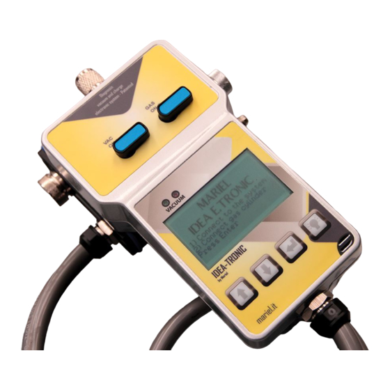
DESCRIPTION OF THE DEVICE IDEA TRONIC is an “integrated” device composed by two connected parts, a base and a hand-held equipment which, once connected to any refrigerating or air-conditioning system will allow you, without more disconnecting, to: 1) RECOVER THE REFRIGERANT GAS, 2) MAKE THE VACUUM, 3) CHECK FOR POSSIBLE LEAKS, 4) MAKE THE CHARGE WITH GRAM ACCURACY, 5) CHECK IF THE CARRIED OUT CHARGE IS CORRECT. -
Page 5: Components
COMPONENTS OF THE KIT Q.ty DESCRIPTION Pic. CODE Complete device, 2 parts: base / hand-held equipment IDEAT Brass adapter 5/16” F - 1/8“ M. - with aerosol M. connection ADATTATORI5/16 Brass adapter 1/4” F - 1/8“ M. - with aerosol M. connection ADATTATORI Nipple 1/4”... -
Page 6: Connection Of The Base To The Vacuum Pump
(point 4). 3 - Connect the yellow hose (point 1) to the 1A nut and to the vacuum connecting port of the Idea Tronic (point 2). 4 - Select the appropriate reduction before screwing the cylinder (check page 8). -
Page 7: Switching On The Equipment
SWITCHING ON OF THE EQUIPMENT Move the power switch to position “1” and wait for instructions that appear on the display (starting screen). LANGUAGE AND/OR CONTRAST MODIFICATION If you need to change the language or to increase / decrease the display contrast, press the two keys with icons “... -
Page 8: Connection Of 1 - 2 Kg. Cylinders
CONNECTION OF 1 - 2 KG. CYLINDERS NB: Connect the appropriate adapter R134 - R600a: do not connect any adapter. R22 - R422B - R407C - R404A : 1/4” F. Sae adapter R410A : 5/16” SAE F. adapter... -
Page 9: Connection Of 5 - 10 - 12 - 40 Kg. Cylinders
80 kg. scale (optional at page 18). After vacuum procedure, open the GAS tap to make charge procedure without disconnecting from the system. It is at the operator discretion to keep the IDEA TRONIC switched on or switched off. -
Page 10: Choice Of Refrigerant Fluid - Bt, Tn, Ac And Charge Method
You will then be asked to select the opportune charge method, it means by weight, if you work with 1 or 2 kg. cylinders screwed on IDEA TRONIC, or by pressure, if you do not know the quantity of refrigerant fluid to fill inside the system and/or if you use cylinders bigger than 2 kg. -
Page 11: System Check Up
SYSTEM CHECK In this screen you can analyze the state of the system on which you will operate; the display will show the following options: Adequate gas Too much gas Problems N.B.: The system check procedure must be carried out with the system switched on (compressor running) after having waited for a few minutes so that the internal pressure has stabilized. -
Page 12: Charge By Weight
If you selected the “charge by weight” option in “SCREEN 2”, proceed with the charge, screwing the refrigerant fluid cylinder on the holder of the IDEA TRONIC device. Set up the refrigerant gas charge in grams which you need to fill inside the system, by sliding “... -
Page 13: Charge By Pressure
(or very close) to those indicated above xxx Bar Bar xxx At this stage the IDEA TRONIC device will emit an acoustic signal indicating that the performance is completed (Picture 3). Use with 5 - 12 - 40 Kg. cylinders... -
Page 14: Refrigerant Recovery Procedure
RECOVERY OF THE REFRIGERANT FLUID If you need to perform the refrigerant fluid recovery operation, you must use the 3 ways adapter supplied as optional (Picture 2), which connects the IDEA TRONIC device, the recovery unit and the vacuum pump simultaneously. -
Page 15: Check Of Special Systems
CHECK OF SPECIAL SYSTEMS Idea Tronic has been developed in order to operate in traditional equipment and condi- tions. The diagnosis displayed on the screen, ADEQUATE GAS, TOO MUCH GAS etc. has been calculated on an average operating process for each refrigerant fluid. -
Page 16: Display Light
IMPORTANT: BATTERIES REPLACEMENT The IDEA TRONIC device operates with n. 4 batteries mod. AA situated in the reverse side. When the batteries are going to deplete, in the display starts to flash a visual symbol (Picture 1). -
Page 17: Decommissioning / Waste Disposal
DEMOLITION: 1 - Follow all operations described in “waste disposal” paragraph; 2 - Disassemble the different components of the IDEA TRONIC device taking care of separating them for typology (e.g.: ferrous components, PVC, aluminium, etc.).NOTE: For disposal, dispose this equipment in a facility that complies with local, state and... -
Page 18: Optional
OPTIONAL MPDRP2 45 l./min. double stage vacuum pump. RE12A Refrigerant recovery unit for domestic, industrial a n d automotive air-conditioners. Oil-less and air-cooled compressor; it recovers all commonly used refrigerant fluids, including R410A. Protection of the compressor in case of abnormalities and excessive pressure. - Page 19 MA29 3 ways adapter for gauge connection MA28 3 ways valve for vacuum pump and recovy unit simultaneous connection D1004 Blue low pressure gauge (R600a) D1006 Blue low pressure gauge (R410A) D1008 Blue low pressure gauge (R134a-R404A-R422B-R407C)
- Page 20 Manufactured by MARIEL srl Via Olubi, 5 28013 Gattico (NO) ITALY www.mariel.it...
Need help?
Do you have a question about the Idea Tronic and is the answer not in the manual?
Questions and answers