Advertisement
Quick Links
If the Centurion Controller and Display Modules are already installed, skip the Installation section and go to the
section titled Before Starting the Equipment for the First Time.
Installation
The following instructions will guide you through installing the Centurion C5 controller, display and additional
communication modules.
For wiring connections, please open the appropriate Installation Manual file on the white thumb drive provided.
No special cables are required. The Centurion system is designed for use within a weatherproof enclosure only.
Basic Components Include:
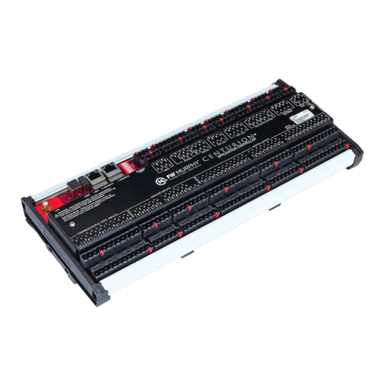
Centurion C5 Controller Module
™
M-VIEW
Display Module
Optional Components Include:
MX4-R2 (Interchange Communication Control Module)
MX5-R2 (Interchange Communication Control Module)
Before installing the product, inspect each item for damage which sometimes occurs during shipping.
Centurion C5 Controller Module
The Centurion Module Controller must be mounted in an enclosure meeting the requirements of IP54 or greater
according to the intended use and environmental conditions in accordance with standard UL 60529 and only
accessible by use of a tool.
Operating Temperature 40° to 185° F (-40° to +85° C)
Pressure 80 kPa (0,8 bar) to 110 kPa (1,1 bar)
Air with normal oxygen content, typically 21% v/v
Temperature Class T4
"ic": intrinsic safety, (for EPL Gc)
Increased safety, (for EPL Gc)
The Centurion Controller can be mounted vertically or horizontally on a standard
DIN rail.
Attach the four clamp-type feet along the bottom of the controller to the DIN rail.
We recommend installing rail stops to prevent sliding.
Section 50
2018-12-03
Centurion™ C5 Quick Start Guide
- 1 -
00-02-1033
2019-02-14
Section 50
00-02-1033
Advertisement

Related Manuals for FW Murphy Centurion C5


Summary of Contents for FW Murphy Centurion C5
- Page 1 Before Starting the Equipment for the First Time. Installation The following instructions will guide you through installing the Centurion C5 controller, display and additional communication modules. For wiring connections, please open the appropriate Installation Manual file on the white thumb drive provided.
- Page 2 Optional: MX4-R2 / MX5-R2 Modules The module must be mounted in an enclosure meeting the requirements of IP54 or greater according to its intended use and environmental conditions in accordance with standard UL 60529 and only accessible by the use of a tool.
- Page 3 M-VIEW Display Dimensions MV-5-C, M-VIEW Monochrome LCD MV-7T, M-VIEW Touch Series MV-10T, M-VIEW Touch Series Section 50 00-02-1033 2018-12-03 - 3 -...
-
Page 4: Install The Display
4. If thread lock is desired for your application, apply blue polycarbonate compatible thread lock to the threads of the mounting studs. It is not a requirement of installing Centurion C5. 5. Install the locknuts to each mounting stud from the back side of the panel to secure the MV-5-C housing. - Page 5 MV-7T and MV-10T Displays Through-Panel Mount Once the cutout is prepared in the panel, the display can be mounted in the cutout and secured with mounting clips. 1. Inspect the O-ring on the display and ensure it is free from any nicks and properly secured in position. 2.
- Page 6 Stand Mount Four mount-tapped screw holes (M4 x 0.7, 5 mm deep) are located on the rear of the panels for stand or wall mounting. Tapped screw hole locations MV-7T MV-10T Section 50 00-02-1033 2018-12-03 - 6 -...
- Page 7 Communications and Security Access The display module is a highly integrated operator interface specially programmed to complement and support the Centurion controller. The primary purpose of the display is to: View controller operational information View/edit controller operational parameters ...
- Page 8 15 seconds. b. From the Centurion Home / Gage screen, touch the Arrow key to scroll left until you find the screen FW Murphy – MVIEW screen. c. Verify that the configuration description matches the one you previously recorded from the drawing legend.
- Page 9 4. Press the Setup Enter key to open the Password screen. a. Use the Arrow keys to enter your password. Default passwords are: Operator-164; Super User-133. If further details are needed, see Display Passwords. 5. Once the password is entered, the display opens the Setpoints Setup screen. Use the right and left Arrow keys to find the screen you want to view / edit.
- Page 10 7. Start the unit. (always armed) a. Clear any Alarms Class A faults from the system. On the display, the Unit State will read Panel Ready if no Class A shutdown condition exist. b. Press and hold the Run/Stop key on the display for 2 seconds. This will initiate the start cycle.
- Page 11 User-Configurable Screens The Centurion has (9) user-configurable pages of (4) types. The Centurion Configuration Tool software allows users to configure up to nine (9) screens with controller input signal groupings. Possible custom screen types may include: a) Custom Line by Line allows users to display process data in a list format with description and value.
- Page 12 Setup – MV-7T and MV-10T Displays Read and follow steps in the order listed. 1. Locate the system drawing inside the panel and verify its drawing number matches the sticker on the lower front panel. 2. Locate the legend of the drawing and find the configuration description. Record this description. 3.
- Page 13 4. Open the following list of screens to verify or change the factory settings as needed for your site location. a. We suggest you record these values in the Sequence of Operation. This gives you a reference of any changed settings from the factory default. b.
- Page 14 Faults, Stops and Alarms Normal Stop When a normal stop is issued and the unit is running, the system will start a normal shut-down sequence. 1. To issue a normal stop, touch and hold the Run Stop icon on the display for 2 seconds. 2.
- Page 15 User-Configurable Screens The Centurion has (9) user-configurable pages of (4) types. The Centurion Configuration Tool software allows users to configure up to nine (9) screens with controller input signal groupings. Possible custom screen types may include: a) Custom Line by Line allows user to display process data in a list format with description and value.
Need help?
Do you have a question about the Centurion C5 and is the answer not in the manual?
Questions and answers