Table of Contents
Advertisement
Quick Links
Warning: The Motor Torque Module can only be used in
conjunction with a Motor Control Module (MCM). The
MCM must be installed before installation of the Motor
Torque Module. For Motor Control Module installation,
see Field Installation Manual 555M.
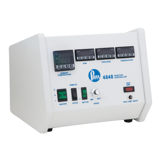
Meter Installation in 4848 Reactor
Controller
1. Unplug the power cord of the 4848 Controller.
Remove the (2) screws located on the top/front
cover at the rear corners of the controller. Gen-
tly lift the cover forward, which is hinged at the
bottom, taking care not to apply tension on any
internal wiring.
2. If applicable, remove and discard the black hole
plug on the sloped front panel above the "PRES-
SURE" or "TEMPERATURE" text. This can be
done by pinching the clasps on the back of the
plug from the inside of the front plate. Place
"MOTOR OUTPUT" label over existing text.
Installation Instructions for Motor Torque
Module (MTM) in a 4848 Reactor Controller
3. Insert the MTM module (2084E) through the
panel cutout, from outside in, making sure the
rubber gasket is on the outside of the controller
front panel. (If wires are preinstalled, remove the
terminal connector by releasing the tabs on the
sides of the module and gently pulling the termi-
nal connector off. Reference photos below.) Slide
the white mounting bracket onto the module with
the mounting screws pointing towards the front
panel. Slide the mounting bracket forward until
it touches the controller panel. The clasps on the
mounting bracket should align with the groves
on the module. Gently tighten the screws until
the module is held into place. (If removed, reat-
tach the terminal connector.)
Terminal Connector Removal
560M
Advertisement
Table of Contents

Related Manuals for parr 4848

Summary of Contents for parr 4848
- Page 1 Slide the mounting bracket forward until it touches the controller panel. The clasps on the 1. Unplug the power cord of the 4848 Controller. mounting bracket should align with the groves Remove the (2) screws located on the top/front on the module.
- Page 2 MTM Installation Meter Installation in 4848 Reactor Controller (Continued) Meter Installation Diagram Side Panel Removal This will require loosening the four nuts on the side The left side panel should be removed to get access panel using a nut driver (two on the bottom and two to the isolation board.
- Page 3 MTM Installation Wiring Installation in 4848 Reactor Controller 1-RED 2-BLACK 4-BLACK 100-240 VAC POWER 3-WHITE 6-BLACK - RS485 5-WHITE 2084E MOTOR OUTPUT DPM Wiring Diagram for 2082E Meter TOTAL COLOR GAGE LENGTH 18.5 ORANGE STRIP .23 STRIP .35 2067E (T6/4)
- Page 4 MTM Installation Wiring Installation in 4848 Reactor that has both ends stripped, and attach one end to the 2084E meter. White wire #5 to terminal Controller (Continued) #11 and black wire #6 to terminal #12. (This may already be connected for your convenience.) 1.
- Page 5 Close the controller and replace the two screws on not, adjust the “tPoF” setting (press set and then the top plate. Plug the 4848 controller back in, and return until it shows tPoF) until it does read zero. turn it on. The MTM display should read approxi- mately zero when the motor is not turning.
- Page 6 MTM Installation Module Operation Select Comment Mode type/value Keys command: PrtY Even Parity bit setting 1. Press “SET” to select StoP Stop bit setting 2. Press return key move to next operation mode 3. Up/Down arrow keys to adjust value or select For 90VDC motor, 115VAC, tP-H = 142.9 type For 180VDC motor, 230VAC, tP-H = 120.4...
- Page 7 MTM Installation This page intentionally left blank. w w w . p a r r i n s t . c o m...
- Page 8 Revision 08/21/12...
Need help?
Do you have a question about the 4848 and is the answer not in the manual?
Questions and answers
Is there a command for changing the motor from clockwise to anti-colockwise direction on Parr 4848?