Table of Contents
Advertisement
Quick Links
Advertisement
Table of Contents

Related Manuals for Masterclock RC500


Summary of Contents for Masterclock RC500
- Page 1 Masterclock RC 500 User Manual – v2014.01.01...
-
Page 2: Table Of Contents
See important limited warranty information starting on page 38. Masterclock RC 500 User Manual – v2014.01.01... -
Page 3: Introduction
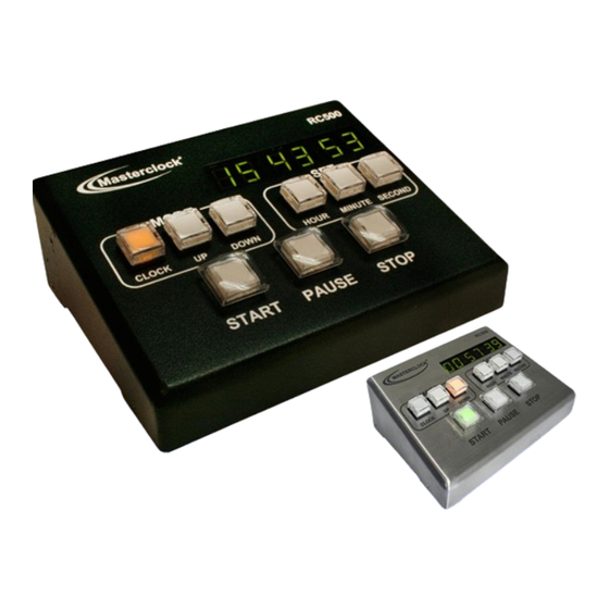
Introduction The RC500 is a programmable, single channel, timer control unit. It remotely communicates with TCDS or NTDS digital time displays, providing count-up, count- down and count-to capabilities. FEATURES • Reference time input from NTP or stand alone with internal oscillator •... -
Page 4: Installation
Communications o CAT5 Ethernet patch cable (NTDS series) 6P6C modular cable (TCDS series) Cat5 Ethernet patch cable || CD with user manual and software || AC power cord with IEC plug ____ Masterclock RC 500 User Manual – v2014.01.01... - Page 5 NTP time display) PoE (optional) models Network Installation You may install the RC500 on your desk top. Attach Some users will connect their RC500 power and communication at the back according to to a network for external time these specs: reference.
- Page 6 TCDS and NTDS digital display clocks NTDS digital display clocks Masterclock RC 500 User Manual – v2014.01.01...
-
Page 7: Interface
Interface The top panel provides immediate access to all major RC500 functions. The panel consists of a 6 digit, 7 segments LED display along with three sets of pushbuttons. Status LED The colons on the LED display are used to alert the user of lock to time reference... - Page 8 There are three action buttons: START, PAUSE and STOP. Set Description START Initiate or resume the count routine. PAUSE Pause the running count. STOP Terminate the count routine and reset preset for next routine. Masterclock RC 500 User Manual – v2014.01.01...
- Page 9 RS485 COMMUNICATION TCDS series of digital time displays are connected to the Do not connect more than one RC RC500 using the RJ12 port and a 6 wire (6P6C) straight- 500 to the same splitter The RC500 through modular cable.
-
Page 10: Control Button Details
Press [START] to send a command to the remote display and start the routine. The display will show the running count. At the end of the routine, the display on the RC500 and remote display will flash three times and hold for a command. - Page 11 Press [START] to send a command to the remote display and start the routine. The display will show the running count. At the end of the routine, the display on the RC500 and remote display will flash three times and hold for a command.
-
Page 12: Count To Time
1:30pm program the unit to 13:30. At the end of the routine, the [DOWN] button will continue to flash indicating the RC500 is currently in Count to Time mode. Press the [START] button to send a command to the remote display and start the Count to Time. - Page 13 To use the custom time feature, any external time reference (i.e. time stamp) has to be removed or disabled. If the RC500 is receiving time stamps, it will display this time, not the custom time entered.
- Page 14 Standalone Menu Display Properties The RC500 can be customized to display time in a variety of formats Default Settings and brightness levels. To enter the configuration menu press and hold [CLOCK] for approximately 2 seconds. Press [DOWN] to cycle through the configuration menu.
- Page 15 This feature will allow a “0” to be displayed for the first digit, between the hours of 1 and 9. _______ The RC500 “Display Properties” will not affect the remote clock display settings. Changes made using WinDiscovery will over-write the standalone settings and vice versa.
- Page 16 1. Insert the CD that shipped with your network clock. 2. Run the “setup.exe” application from the CD. 3. By default, the setup utility will suggest installing files to C:\Program Files\Masterclock\WinDiscovery. 4. Click the [OKAY] button Masterclock RC 500 User Manual – v2014.01.01...
- Page 17 When complete, a list of device families and groups will be displayed in the left pane of the WinDiscovery window. RC500 will be displayed along with any other devices that are on the network Click [Discover] to view NTP devices on your network.
- Page 18 Right click the device name and the properties window will open. Click on a menu choice to open the window for that function. The choices are: Properties Network Settings Device Settings Set Password Set Time/Date Status Reset Device Use the [Cancel] button to exit the screen without applying changes. Masterclock RC 500 User Manual – v2014.01.01...
- Page 19 [Save] button or the [Save and Close] button, prior to clicking the [Exit] button. SET PASSWORD Each Masterclock device in your network may have its own password (see the “Properties” window to [Set Password]) or you may create a Global Password on the “Discover”...
- Page 20 To use global password, click [Global Password] from the main window of WinDiscovery. The global password being used must match the password on all the devices being administered. For example, on any new system being installed, the factory default password on all devices is “public”. Masterclock RC 500 User Manual – v2014.01.01...
- Page 21 STATUS See “Status” window, page 34 RESET DEVICE See ”Reset Device” window, page 32. MANAGING DEVICE To open “Device Settings” and show [Configurable Options] buttons, double left click on device in “Discovery Window” Masterclock RC 500 User Manual – v2014.01.01...
- Page 22 Use the [Cancel] button to exit the screen without applying changes. INPUT CONTROL The [Input Control] button provides access to the “Input Control” window, which provides button for NTP Client. Device Settings – Input Control is circled. Clock Control is surrounded by yellow Masterclock RC 500 User Manual – v2014.01.01...
- Page 23 By default, the NTP clock will operate only in Unicast/Query mode using server port 123.This mode is selected exclusively when neither the listen for NTP broadcast nor the listen for NTP multicast modes are selected. Masterclock RC 500 User Manual – v2014.01.01...
- Page 24 While listening to NTP broadcasts/multicasts, the network clock cannot be configured to query the time server. Some NTP/SNTP clients will expect NTP servers to operate on port 123 and cannot be configured to use alternate ports. Masterclock RC 500 User Manual – v2014.01.01...
- Page 25 While listening to NTP broadcasts/multicasts, the network clock cannot be configured to query the time server. Some NTP/SNTP clients will expect NTP servers to operate on port 123 and cannot be configured to use alternate ports. Masterclock RC 500 User Manual – v2014.01.01...
- Page 26 This allows for setting the NTP mode and parameters of the SNTP client in the network clock. The default TCP/UDP port for NTP service is 123. Some NTP/SNTP servers will expect NTP clients to operate on port 123. Masterclock RC 500 User Manual – v2014.01.01...
- Page 27 The upper left-half corner allows you to adjust the brightness of the LEDs and button illumination. The options in this configuration region may be grayed out; this indicates unavailable options for this model of network device. Masterclock RC 500 User Manual – v2014.01.01...
- Page 28 RC500 “Clock Assignment” window. Use this menu to configure which remote NTP clock displays will respond to the RC500 commands. The list in the left column is the available clock displays and the right column show the devices assigned to the RC500.
- Page 29 By clicking [OK], all RC500s and clock displays on the network will have their assignments cleared. This is a global “clear all” and in order for a RC500 to control a clock display, it will need to go through the “Clock Assignment” configuration...
- Page 30 5. Click [OK] to close the Window. The DST rules will be saved when you click either the [Apply] button or the [Apply and Close] button on the “Device Settings” window. US/Canada DST standard EU DST standard Masterclock RC 500 User Manual – v2014.01.01...
-
Page 31: Standalone Configuration
(Standalone Configuration) and operate without a reference input TCXO AND RTC CIRCUIT The RC500 contains a precision TCXO and RTC circuit allowing the clock to maintain an accuracy of ±1 minute per year to the last known Time Code input (±165 mS per day) when a time reference is not preset or cannot be decoded (i.e. - Page 32 Alternatively, if you are not in the “Administrative Functions” window, but are viewing the list of devices after pressing the [Discover] button, simply right click on the device you are interested in and select the [Reset Device] button. Masterclock RC 500 User Manual – v2014.01.01...
- Page 33 Reset Configuration to Factory Default In some situations it may be necessary to return the unit to factory default settings. The unit will go through an initialization process. Next, the RC500 will show the time on the display. SET TO DEFAULT CONFIGURATION...
- Page 34 This status update is not precise, but is intended to give you a view of the device display for troubleshooting purposes. The Status also shows the active NTP server; primary and/or secondary, the current synchronization status and time adjustment information. Masterclock RC 500 User Manual – v2014.01.01...
- Page 35 WinDiscovery window. To determine the cause of why the device received a “169.254.xxx.xxx” address the user should display the status of the clock. Near the bottom of the Status window the error will be displayed Masterclock RC 500 User Manual – v2014.01.01...
-
Page 36: Telnet
By default, Microsoft Windows 7 has the Telnet Client disabled. To enable, open Control Panel, click on “Programs”, click on “Turn Windows features on or off”, check [√] Telnet Client and click [OK]. Masterclock RC 500 User Manual – v2014.01.01... - Page 37 (such as “timezone” then press [Enter] or [Return]. Follow the command with a “?” to show more options and the command string. Shown at left, “timezone” command with results and “timezone?”command with results Masterclock RC 500 User Manual – v2014.01.01...
- Page 38 Show or change the password. ping - Ping to a specified host This is useful in situations where the communication path from the network clock to the NTP server is in question. properties Show the device properties. Masterclock RC 500 User Manual – v2014.01.01...
- Page 39 Show or change the leading zero setting. Displays the list of Telnet commands. Follow a command with “/?” to see specific help for that command. help Displays brief help when followed by a command. Masterclock RC 500 User Manual – v2014.01.01...
-
Page 40: Specifications
Consumption ............ 5 W Connector ............Universal IEC input connector RJ45 ..............PoE (Power over Ethernet) There are no user serviceable parts inside the RC500 Timer Control Unit. Please contact Masterclock, Inc. if you require servicing or repair Internal Battery Circuit... -
Page 41: Problems - Troubleshooting
Possible reasons/solutions: 1. The RC500 is not currently connected to a valid time reference. 2. There is a problem with the cabling between the RC500 and the time reference. Verify that all cables and connectors are in good condition. Unable to lock to time code Possible reasons/solutions: 1. - Page 42 UDP broadcasts across networks-currently; this capability is required to use WinDiscovery for enterprise-level management of Masterclock, Inc. network appliances. If you are running a personal firewall product, such as Zone Alarm or Black ICE, or the built in Windows firewall you must adjust their configuration to pass through (both directions) UDP traffic on port 6163.
- Page 43 DHCP configuration. 3. If the RC500 has not been configured with a least one valid DNS server (or that DNS server is down) hesitations similar to those described in #1 will occur. At least one valid DNS server is required for operation.
- Page 44 To remove labels, stickers, etc., the use of kerosene, naphtha or petroleum spirits is generally effective. When the solvent will not penetrate sticker material, apply heat (hair dryer) to soften the adhesive and promote removal. Gasoline should never be used. Masterclock RC 500 User Manual – v2014.01.01...
- Page 45 Service Information We sincerely hope that you never experience a problem with any Masterclock product. If you do need service, contact Masterclock’s Technical Support team. A trained specialist will help you to quickly determine the source of the problem. Many problems are easily resolved with a single phone call or email.
- Page 46 Masterclock will, at its option, either repair or replace products that prove to be defective. Should Masterclock be unable to repair or replace the product within a reasonable amount of time, the customer's alternate remedy shall be a refund of the purchase price upon return of the product to Masterclock.
- Page 47 Compliance Masterclock RC 500 User Manual – v2014.01.01...
- Page 48 EN 61000-3-3:2008 (Voltage Fluctuations and Flicker) Low voltage directive 2006/95/EC Tested and Conforms to the following Safety standards: EN 60950-1:2006 (Safety of Information Technology Equipment) Certificated By CELAB www.celab.com ® UCN = xxxxxxxxxxxxxxxxxxxxx Masterclock RC 500 User Manual – v2014.01.01...
- Page 49 WEEE Waste Electrical and Electronic Equipment Directive (WEEE) 2002/95/EC The RC500 is considered WEEE Category 9 (Monitoring and Control Instruments Equipment) as defined by the WEEE Directive and therefore fall within the scope of the WEEE Directive.
- Page 50 Copyrights Copyright © 2011 Masterclock, Inc. All rights reserved. No part of this publication may be reproduced, stored in a retrieval system or transmitted in any form or by any means, electronic, mechanical, photocopying, recording or otherwise, without the prior written consent of Masterclock, Inc.
Need help?
Do you have a question about the RC500 and is the answer not in the manual?
Questions and answers