Table of Contents
Advertisement
Quick Links
Advertisement
Table of Contents

Subscribe to Our Youtube Channel
Summary of Contents for Vortex VN2000
- Page 1 VN2000 Flow Meters Transmitter User Manual VRX-UM-02233-EN-02 (June 2017)
- Page 2 VN2000 Flow Meters, Transmitter Page ii VRX-UM-02233-EN-02 June 2017...
-
Page 3: Table Of Contents
Removing VN2000 Transmitter Electronics . . . . . . . . . . . . . . . . . . - Page 4 VN2000 Flow Meters, Transmitter Page iv VRX-UM-02233-EN-02 June 2017...
-
Page 5: Purpose Of This Document
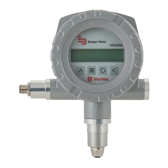
INTRODUCTION The VN2000 Transmitter is supplied with all vortex flow meters . It is designed to be located on the head of the meter or remotely mounted from the meter, for easy viewing and access . Three configurations are available: •... -
Page 6: Installing The Transmitter
Installing the Transmitter INSTTLLING THE TRTNSMITTER The remote transmitter enclosure has a mounting bracket for wall mounting . Locate the enclosure within 30 feet of the pipeline sensor and at eye level for easy viewing and access to the control panel keys for programming . Remote Transmitter To Power... -
Page 7: Wiring
Wiring WIRING The transmitter ships with a cable that has a connector on one end and flying leads with 4 or 5 wires on the other end . Use this cable to wire the power and outputs . The transmitter is available with two output options: •... -
Page 8: Connecting Cables
Connecting Cables CONNECTING CTBLES Connecting to the flow meter is easy using our plug-and-play design . No internal wiring is required . All cables are included with the meter . Cable Description Replacement Part Number Transmitter power, 4…20 mA 4-pin cable, 9 ft (3 m) VNA-CBL-PWR-AA-09 Transmitter power, Modbus RTU 5-pin cable, 9 ft (3 m) VNA-CBL-PWR-MA-09... -
Page 9: Operating The Vn2000 Transmitter
Operating the VN2000 Transmitter OPERTTING THE VN2000 TRTNSMITTER VN2000 Figure 4: VN2000 transmitter Control Panel Keys To access the control panel keys, unscrew and remove the faceplate cover . In Password or Program mode, press the Up Trrow key to increment the selected digit by one . -
Page 10: Display Modes
Operating the VN2000 Transmitter Display Modes The VN2000 Transmitter has a 32-character display that is organized as two rows of 16 characters each . The display software is designed to operate in one of three modes . OTEE: The options available in the Programming mode will vary, depending on the media (steam, gas or liquid) for which the transmitter was configured: •... - Page 11 Operating the VN2000 Transmitter In all other cases, the option to display Temperature or Pressure is not available . To activate the option to display Temperature or Pressure, press Up Trrow to scroll through three display patterns: • Totalizer value only •...
-
Page 12: Programming Mode Level 1
Operating the VN2000 Transmitter Programming Mode Level 1 OTEE: Currently, the word “Pressure” displays on the screen, but the Pressure feature is not yet supported . OTEE: The options available in the Programming mode will vary, depending on the fluid type (steam, gas or liquid) and... - Page 13 Operating the VN2000 Transmitter Units of Measure (Engineering Units) Press Up Trrow to scroll through the engineering units . Stop pressing when the proper unit is displayed . That unit is now the unit of measure . When the units are changed, the Flow Total and Flow Rate are automatically adjusted .
- Page 14 To change the K-Factor, press Left Trrow to move the cursor under the digit to be changed . Press Up Trrow to change the digit . If the K-Factor does not match the “VN2000 SF” found on the bottom right of your sizing sheet, contact the manufacturer .
-
Page 15: Programming Mode Level 2 (A1-Ss78Mb-C)
Table 6: Mass flow mode options Flow Tdjust (Tdjust Flow?) The Flow Adjust option allows for field calibration of each vortex flow meter without changing core application data, such as the K-factor . ADJUST FLOW? Use Flow Adjust only as a last resort if there can be no change to the location of the installation or overall flow profile due to: •... - Page 16 2 . Press Left Trrow to move the cursor and Up Trrow to change the digits to the desired flow rate . 3 . Press Menu and let the meter come back to Flow Rate and Flow Total . The VN2000 Transmitter adjusts the internal calibration curve, allowing the new flow rate to appear . Set Ratio 1 .
- Page 17 Has settings range from 0…7, with 0 being the most sensitive and 7 being the least sensitive . The typical Vortex Threshold setting for liquid, gases and steam is 3 . If the setting is not at 3, consult the factory .
-
Page 18: Programming Mode Level 3 (A1-Ss78Mb-S)
Operating the VN2000 Transmitter Programming Mode Level 3 (T1-SS78MB-S) With the power ON and Flow Rate and Flow Total displayed, press Left Trrow, then Up Trrow . When the message “A1-SS78MB-S” displays, press Menu to scroll through the Level 3 programming options: •... - Page 19 To change the K-Factor, press Left Trrow to move the cursor under the digit to be changed . Press Up Trrow to change the digit . If the K-Factor does not match the “VN2000 SF” found on the bottom right of your sizing sheet, contact the manufacturer .
- Page 20 NOT be changed . If the incorrect fluid type is selected, please contact the factory immediately . Modbus Tddress Enter the Modbus RTU address . See the “VN2000 Flow Meters Modbus User Manual . ” Settings Initially, the meter shows field settings that have been factory-set for your particular application parameters .
-
Page 21: Specifications
Specifications SPECIFICTTIONS 2×16 characters reflective display Rotatable display Display Flow rate: 6 digits with decimal Totalizer Keypad 4 membrane buttons Power 14…36 V DC Operating 32…140° F (0… 60° C) Temperature 5…100% relative humidity non-condensing One 4…20 mA, 10…36V max load, 24-bit resolution Output Adjust the 4 mA and 20 mA signal from the keypad and zero out any anomalies found between the meter and the monitoring device... -
Page 22: Alarm Messages
(20 mA) setting in operation, if this condition is not expected . the VN2000 Transmitter representing the 20 mA Change the max flow (20 mA) setting, if needed . output . The flow meter continues to display an unlimited maximum flow rate . -
Page 23: Troubleshooting
. Table 12: Troubleshooting Transmitters and replacement electronics are available . Please contact the factory for proper selection . REMOVING VN2000 TRTNSMITTER ELECTRONICS 1 . Turn OFF power to the transmitter . 2 . Remove the enclosure lid . -
Page 24: North American Pipe Schedules
North American Pipe Schedules NORTH TMERICTN PIPE SCHEDULES Steel, Stainless Steel, PVC Pipe, Standard Classes SCH 60 X STG. SCH 80 SCH 100 SCH 120/140 SCH 180 Wall Wall Wall Wall Wall Wall 1 .315 0 .957 0 .179 0 .957 0 .179 0 .815 0 .250... - Page 25 North American Pipe Schedules Steel, Stainless Steel, PVC Pipe, Standard Classes (continued) SCH 10 SCH 5 SCH 20 SCH 30 SCH 40 (Lt Wall) Wall Wall Wall Wall Wall Wall 1 .315 1 .185 0 .065 1 .097 0 .109 1 .049 1 .049 0 .133...
- Page 26 North American Pipe Schedules Copper Tubing, Copper and Brass Pipe, Tluminum Copper Tubing Copper Tubing Copper Copper Nominal Nominal & Brass Tlum. & Brass Tlum. Diameter Diameter Pipe Pipe Type Type 0 .625 0 .625 0 .625 0 .840 3 .625 3 .625 3 .625 4 .000...
- Page 27 North American Pipe Schedules Cast Iron Pipe, Standard Classes, 3…20 inch Class Size 3 .80 3 .96 3 .96 3 .96 Wall 0 .39 0 .42 0 .45 0 .48 — — — — 3 .02 3 .12 3 .06 3 .00 4 .80 5 .00...
- Page 28 VN2000 Flow Meters, Transmitter Cast Iron Pipe, Standard Classes, 24…84 inch Class Size 25 .80 25 .80 26 .32 26 .32 26 .90 26 .90 27 .76 27 .76 Wall 0 .76 0 .98 1 .05 1 .16 1 .31 1 .45...
Need help?
Do you have a question about the VN2000 and is the answer not in the manual?
Questions and answers