Table of Contents
Advertisement
Quick Links
Tel: +44 (0)1962 736736 Fax: +44 (0)1962 736737 Email: sales@influxmeasurements.com
A GUIDE TO THE INSTALLATION, OPERATION & MAINTENANCE OF
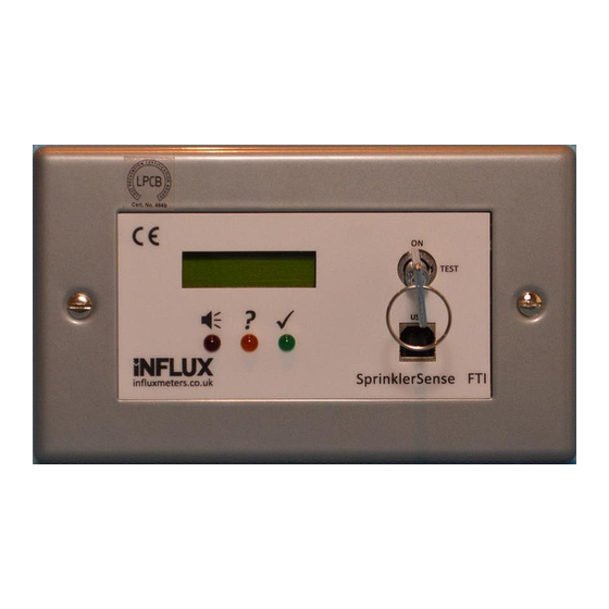
SprinklerSense Fixed Test Interface Unit, FTI
FOR USE WITH SPDB30 & SPDB90 TYPE FLOW SWITCHES
Contents:
1
1.1
1.2
1.3
1.4
2
2.1
2.2
3
IOM FTI Iss.1
MEASUREMENTS LTD
1A Bennett House, The Dean, Alresford, Hampshire, UK. SO24 9BQ
October 2018
Cert. No. 464b
Page
2
2
2
2
4
5
5
6
8
Page 1 of 8
Advertisement
Table of Contents

Summary of Contents for INFLUX MEASUREMENTS SprinklerSense FTI
- Page 1 MEASUREMENTS LTD Cert. No. 464b 1A Bennett House, The Dean, Alresford, Hampshire, UK. SO24 9BQ Tel: +44 (0)1962 736736 Fax: +44 (0)1962 736737 Email: sales@influxmeasurements.com A GUIDE TO THE INSTALLATION, OPERATION & MAINTENANCE OF SprinklerSense Fixed Test Interface Unit, FTI FOR USE WITH SPDB30 &...
-
Page 2: Specification & Operation
Specification & Operation Introduction The SprinklerSense FTI is designed specifically for use with Influx SPDB30 and SPDB90 type LPCB approved flow switches. The unit is permanently wall mounted at an easily accessible height to provide a user interface to access the self-test features of the flow switch and provide repeat relay contacts for both the Flow and Error outputs. - Page 3 Flow Switch Check While the green LED is flashing, turning the key to TEST will start a flow switch check. This should only be carried out by or with the permission of Fire Safety personnel, after the main panel has been set ready for the test.
-
Page 4: Pc Connection Via Usb
PC Connection via USB If a PC with the SprinklerSense PTE application installed is connected via a USB lead, the key must be turned to TEST to enable the connection. This should only be enabled after the PC is on and connected, and the FTI display shows “USB OK”. -
Page 5: Installation
Installation Mechanical The 2 Gang size fascia plate is supplied with a matching surface mounted box. If required an alternative 2 Gang type box can be used with a minimum depth of 35mm. The box should be mounted in an easily accessible position where it is not likely to become wet in normal use. -
Page 6: Electrical & Power Supply
Electrical & Power Supply THIS IS AN EXTRA-LOW VOLTAGE DEVICE, DO NOT CONNECT TO MAINS VOLTAGES OR CONNECT MAINS VOLTAGES WITHIN THE BOX. Power Supply and Battery The SprinklerSense system requires a D.C. power supply connection within the range of 9 to 30 Volts. This allows it to be supplied using proprietary battery backup systems of either 12 or 24V DC. - Page 7 Flow Switch and FTI System Wiring Diagram: Remote Key-Switch Terminals Two terminals are provided on a separate block (J5) for remote key-switch actuation. These terminals must only be connected to volt-free contacts such as a mechanical switch or relay contacts. Connection to other types of circuit may result in failure of the FTI.
-
Page 8: Maintenance
Maintenance If the FTI fails to indicate or respond, first check that the power supply is correct and turned on. If the Remote Key-Switch input is connected, disconnect and try unit again. If the unit still does not function it should be replaced by a new unit. FTI units are interchangeable and require no setting up.
Need help?
Do you have a question about the SprinklerSense FTI and is the answer not in the manual?
Questions and answers