Table of Contents
Advertisement
Advertisement
Table of Contents

Summary of Contents for Sewhacnm SI 400
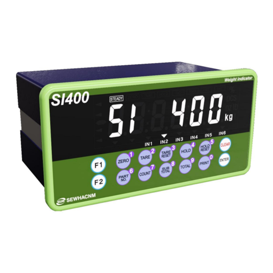
- Page 1 Digital Indicator SI 400 User Manual Ver. 1.0 2014.08.25...
-
Page 2: Table Of Contents
SI 400 DIGITAL INDICATOR CONTENTS 1.Before Installation ···································································· - 3 - 2.Introduction ··········································································· - 4 - Introduction 2-1. ··········································································· - 4 - 2-2.Cautions ················································································· - 4 - 2-3.Feature ·················································································· - 4 - 3.Specification ··········································································· - 5 - 4.Installation ··········································································· - 11 - Dimension &... -
Page 3: Before Installation
This manual may be changed as the version is upgraded, without previous notice. Inquiries If you have any kinds of inquiries for this model, please contact your local agent or Head Office. Head Office : SEWHACNM CO., LTD. Website : http://www.sewhacnm.co.kr Email : sales@sewhacnm.co.kr... -
Page 4: Introduction
7. Item’s performance will be up-dated continuously base on previous version’s performance. 2-3. Features 1. SI 400 model is standard size indicator which is easy to install on the panel. 2. Front panel is covered with Polycarbonate film, strong against dust and water. -
Page 5: Specification
SI 400 DIGITAL INDICATOR 3. SPECIFICATION 3-1. Specification Content Specification Display Resolution 1/20,000 Internal Resolution 1/2,000,000 (±1,000,000) Input Sensitivity Min 0.1µV/V Max Signal Input Voltage Max 3.0mV/V Load cell Excitation DC +5V Analog Part A/D Conversion Method Sigma-Delta Decimal Point 0, 0.0, 0.00, 0.000... - Page 6 SI 400 DIGITAL INDICATOR 3-2. Option Option1 Serial Interface(RS-422) Serial Interface(RS-485) Option2 Option3 Serial Interface(RS-232) Option4 ETHERNET CARD Option5 Analog Output(0~20mA) Analog Output(0~10V) Option6 Option7 BCD OUT Option8 BIN IN SD Memory card Option9 3-3. Front Panel 3-3-1. Front Panel (Display / Key Pad)
- Page 7 SI 400 DIGITAL INDICATOR 3-3-2. State Lamp CONDITION MARK CONTENT When the weight is stable, ON. STEADY When the current weight is zero, ON. ZERO When the “TARE” function is set, ON. TARE HOLD When the “HOLD” function is set, ON.
- Page 8 SI 400 DIGITAL INDICATOR 3-3-3. Key Operation - Press 4 times within 3secs, to enter to Function setting mode. - Press 4 times within 3secs, to enter to “Hidden function” mode. - Make the weight value to Zero - Number 1...
- Page 9 SI 400 DIGITAL INDICATOR 3-3-4. Hot key Double tare setting (Once tare is set, Another tare is overlapped.) Display the current weight during 5 secs. Print the Sub-total out Print the Grand-total out Delete the Sub-total weight Delete the Grand-total weight Max accumulated weighing count : 999,999times Over 999,999times ...
- Page 10 SI 400 DIGITAL INDICATOR 3-4. Real Panel (5)AnalogOutput (1)POWER (6)Option SERIAL I/F (3)SERIAL I/F (4)LOAD CELL (2)External Input (1) AC Power input terminal (2) External input terminal: User selectable 6EA (Function 233~238) (3) Serial Interface terminal Terminal RS – 232...
-
Page 11: Installation
SI 400 DIGITAL INDICATOR 4. INSTALLATION 4-1. External Dimension & Cutting Size Cutting Size 4-2. Installation Components SI 400 User Manual - 11 -... -
Page 12: Load Cell Installation
SI 400 DIGITAL INDICATOR 4-3 Load cell Installation Load Cell Wire Connection (In case of SEWHACNM’s Load cell) It depends on the manufacturer of load cell, please check the specification. Under Set-up the Load cell, if EXC+ and EXC- have a short circuit, It may cause damage in the indicator.(specially analogue board) -
Page 13: Set-Up
SI 400 DIGITAL INDICATOR 5. SET-UP 5-1. Test Weight Calibration Mode (Using test weight) 5-1-1. Start Test Weight Callibration Mode Remove “CAL-BOLT” on the Rear panel, . When “CALIBR” displays, press key. and press “CAL - LOCK S/W” inside. select “WCAL” and press key. - Page 14 SI 400 DIGITAL INDICATOR 5-1-3. Decimal point and division setting After “DIVI” is displayed, locate the decimal point with keys, and set the division with keys. Press key to save. Max decimal point will be 0.001, and digit can be selected among 1, 2, 5, 10, 20, 50. Digit and decimal point must be fulfilled under the below condition.
- Page 15 SI 400 DIGITAL INDICATOR Indicator will search “DEAE weight” during 10secs automatically to find the best condition. In this step, if there is unstable condition such as some forces or Vibration on the scale part, “ErrorA” will be displayed, and “DEAD value” will not be calculated.
- Page 16 SI 400 DIGITAL INDICATOR Calculate Span value during 10~20 secs. After calculation, span value will be displayed on the When “CALEND” is displayed and display. Then press key. calibration is completed. ※This span value is not a weight value. We recommend to proceed this span value calculation step when “STEADY” is displayed...
- Page 17 SI 400 DIGITAL INDICATOR 5-2. Simulation Calibration Mode (Calibrate without Test weight) With this “Simulation Calibration Mode” you can make simple calibration without any “TEST weight” This calibration mode uses “Load cells’ max capacity” and “Max Output Rate(mV)”, so the weight adjustment degree might be less than “Test weight Calibration”.
- Page 18 SI 400 DIGITAL INDICATOR 5-2-2. Setting “Capacity of Load Cell” After “CAPA” displayed, Check Max Capacity of Load cell, Input the Max Capacity of Load cell. (refer the load cell label, or Test Report.) And press key. In case of multiple pieces of load cells are installed, Please make sum of each load cell’s capacity and make setting with Max Capacity.
- Page 19 SI 400 DIGITAL INDICATOR 5-2-4. Measuring the “DEAD Weight” of Weighing Scale. When “DEAD” displays, Press key, then indicator will calculate dead weight of scale part automatically. (While this process, there should be nothing on the scale part.) 5-2-5. Inputting Max Output ( Rated Output Voltage / mV) After is displayed, Check the Rated output value of Load cell.
- Page 20 SI 400 DIGITAL INDICATOR If input wrong value, there will display “Err-01”, please go back to Setting “Capacity of Load Cell”. After recheck the label of load cell and retry the process. Calculated span value will be displayed. Then press key to finish the calibration step.
-
Page 21: F-Function Setting
SI 400 DIGITAL INDICATOR 5-3. F-FUNCTION Setting 5-3-1. Starting F-FUNCTION Mode Press kye 4 times When “SETUP” is displayed, press key. Function No. Set Value Function No. ↑ or input the function No. by number key (0~9) after select “Function No.” area by pressing key. - Page 22 SI 400 DIGITAL INDICATOR 5-3-2. F-Function List F-LIST Subject Default Contents 01~99 Equipment No. setting – ID No.setting 00:Normal mode Weight–Back up Mode 01: Weight Back up Mode(Zero) 02: Weight Back up Mode(Zero&Tare) 00: Manual: Whenever “Print” key input 01: Auto: At every steady states...
- Page 23 SI 400 DIGITAL INDICATOR 00: Active within 2% of Max Capacity 01: Active within 5% of Max Capacity 02: Active within 10% of Max Capacity Zero key Operation Range 03: Active within 20% of Max Capacity 04: Active within 50% of Max Capacity...
- Page 24 SI 400 DIGITAL INDICATOR 00:Disuse, 01:Zero, 02:Tare, 03:Tare reset, 04:Tare/Tare reset 05:Hold, 06:Hold reset, External Input 3 Setting 07:Hold/Hold reset, 08:Print 09:Sub-total print, 10:Grand-total print 00:Disuse, 01:Zero, 02:Tare, 03:Tare reset, 04:Tare/Tare reset 05:Hold, 06:Hold reset, External Input 4 Setting 07:Hold/Hold reset, 08:Print...
- Page 25 SI 400 DIGITAL INDICATOR 00:Countinuously 01:Single time on every steady state Date transference under stream mode 02:At the first steady point 03:When input print key Modbus Transmit Data MSB/LSB 00:Standard, 01:Change location 00: Data bit8, Stop bit1, Parity bit Non...
- Page 26 SI 400 DIGITAL INDICATOR 00 : Format 1 (19byte) Stream mode DATA Ethernet 01 : Format 2 (22byte) 02 : Format 3 (17byte) Transference Format selection 03 : Format 4 (22byte) (Option Port) 05 : Format 5 (15byte) 00 : Countinuously...
- Page 27 SI 400 DIGITAL INDICATOR Gate Way Setting 2 0~255 Gate Way Setting 3 0~255 Gate Way Setting 4 0~255 Port Setting 0~65000 ◆ Weighing Data Saving time point and print Print input Weighing Data Save Method (Key, Printing out data...
- Page 28 SI 400 DIGITAL INDICATOR DATE(Y,M,D) Check / Modification HF05 Check the date or adjust when it is wrong. TIME(H,M,S) Check / Modification (24Hours) HF06 Check the time or adjust when it is wrong. Password Setting (4digit) Password is required when you enter to hidden function.
-
Page 29: Test Mode
SI 400 DIGITAL INDICATOR 5-4. Test Mode Before starting the TEST mode, please remove operating devices. Analog Value 4times Analog Deviation Check 4times Key Input Check 4times Display Check Test 4times Mode External Input 4times ... -
Page 30: Interface
SI 400 DIGITAL INDICATOR 6. INTERFACE 6-1. Serial Interface 6-1-1. Standard serial interface terminal (1) RS - 232 6-1-2. Option serial interface terminal (1) RS – 232 - 30 -... - Page 31 SI 400 DIGITAL INDICATOR (2) RS – 422 Maximum 32units of Indicators connectable (3) RS – 485 Maximum 32units of Indicators connectable - 31 -...
- Page 32 SI 400 DIGITAL INDICATOR 6-1-1. Data Format (1) Data Format 1 : ID Number is not be transferred. (Refer F-function 305-00) -19byte Header1 Header2 OL : OVER LOAD NT : NET-WEIGHT(Tare is not set) ST : STEADY GS : when setting TARE...
- Page 33 SI 400 DIGITAL INDICATOR (4) CAS Format (22byte) : ID Number (Refer F-function 305-03) -22byte Header1 Header2 OL : OVER LOAD NT : NET-WEIGHT(Tare is not set) ST : STEADY GS : when setting TARE US : UNSTEADY LAMP DISPLAY...
- Page 34 SI 400 DIGITAL INDICATOR 6-1-2. Command Mode Under “Command Mode”, Indicator will recognize the receipt of Order based on 02h(STX) and 03h(ETX) signal, and transfers 06h(ACK), 15h(NAK). . Error Code (Function 304 - 01 or 311 - 01) 0 (30h)
- Page 35 SI 400 DIGITAL INDICATOR 6-1-4. Write Command Length of reception data 305/312 305/312 Subject Command 00,01,03,04 Zero STX ID WZER ETX 8 byte Tare STX ID WTAR ETX 8 byte Tare Reset STX ID WTRS ETX 8 byte Hold STX ID WHOL ETX...
- Page 36 SI 400 DIGITAL INDICATOR 6-1-5. Modbus Memory Map - RO : Read Only - RW : Read Write - Each P/N’s set point can’t over max capacity of Indicator. ex)35.00kg = 3,500 (0xDAC) - When you input date and time, it should be 6digit.
- Page 37 SI 400 DIGITAL INDICATOR 6-1-6. Modbus Memory Register (1) Digital Input Register (Address : 17, Length : 2) Digital input data is indicated by 16bit. INPUT_1 INPUT_2 INPUT_3 INPUT_4 INPUT_5 INPUT_6 (2) Lamp Register (Address : 19, Length : 2) Lamp data is indicated by 32bit.
-
Page 38: Externalinput
SI 400 DIGITAL INDICATOR 6-2. External Input Each External Input funtion setting is F-Funtion 233~238 possible. 6-2-1. External Input configuration 6-2-2. External Input connector connection TERMINAL INPUT IN COM - 38 -... -
Page 39: Currentloop
SI 400 DIGITAL INDICATOR 6-3. Current loop Current loop is suitable for middle distance transmission because stronger than RS-232C against electric noise. (About 100M) Maximum communication speed is 9,600. 6-4-1. Current loop circuit composition 6-4-2. Connection RS232 RS232 RS232 - 39 -... -
Page 40: 6-4.Analog Output Interface (4~20Ma)
SI 400 DIGITAL INDICATOR 6-4. Analogue I-Output Interface : 4~20mA This output card converts weight value to Analog output signal (4~20mA) and transfers to external devices(Recorder, P.L.C), controlled by voltage output. 6-5-1. Specification Output current Accuracy Temperature Max Loaded compensation Impedance 0㎃... -
Page 41: 6-5.Analog Output Interface (0~10V)
SI 400 DIGITAL INDICATOR 6-5. Analog V-Output Interface :0~10V This output card converts weight value to Analog output signal (0~10V) and transfers to external devices(Recorder, P.L.C), controlled by voltage output. 6-6-1. Specification Output Voltage 0~10V DC output Accuracy 1/5,000 Under Calibration mode or “CELL-ERR” condition, Analogue output will not activated. -
Page 42: Printinterface
SI 400 DIGITAL INDICATOR 6-6. Analog output selection (1) On the option board, there is switch for analog output selection 4-20mA or 0-10V. (2) "HF13 Analog output setting" should be changed also. 6-7. Print Interface It can be connected with all kinds of Serial interface printer, but the printing format is already programmed and fixed with SE7200/7300 model. -
Page 43: Binincard
SI 400 DIGITAL INDICATOR 6-8. BIN IN card (Changing Product number) 6-8-1. BIN IN card circuit composition 6-8-2. BIN IN card connection PIN No. Role Function 404-00 Function 404-01 - 43 -... -
Page 44: Bcdoutcard
SI 400 DIGITAL INDICATOR 6-9. BCD OUT Card (Weight data out) (Function 310-00) 6-9-1. Circuit composition 6-9-2. Card switch setting SWITCH BASIC MOTION NON-INVERT HIGH INVERT HIGH 6-9-3. BCD OUT card specification MAX Input Voltage 30V 500mA 6-9-4. BCD OUT card connection Role Pin No. -
Page 45: Ethernet
SI 400 DIGITAL INDICATOR 6-10. Ethernet card Using this Ethernet communcation, indicator and other external devices can be communicate (10/100Mbps). )Function 405~417) Depending on your selection from function 310 (Stream mode or command mode), this function is rely on function 311~313.. - Page 46 SI 400 DIGITAL INDICATOR 6-11-3. Recommanded model Memory Model Form factor Class SanDisk SDHC memory card 4G SDHC Regular BACK UP is recommended because there is limit of memory. How to do memory card format : Connect SD card to PC, and select FORMAT from PC system folder.
-
Page 47: Error & Treatment
SI 400 DIGITAL INDICATOR 7. Error & Treatment 7-1. Load Cell Installation Error Cause Treatment Remarks 1) Load cell broken 1. Input Resistance of 2) Load cell isolation 1) Measure “EXC+” and “EXC-“ is resistance error input/output resistance about 400Ω ±30... - Page 48 SI 400 DIGITAL INDICATOR 7-2. Calibration Process Display Cause Treatment Re-input the Max Capacity, less than When Max capacity/digit value is over 20.00 Eerr01 20,000 (Max Capacity / Digit) Standard weight value is over than Max Re-input Standard weight value with...
- Page 49 SI 400 DIGITAL INDICATOR 7-3. Digital Weighing Indicator Display Cause Treatment 1. Under “TEST” mode 1, check 1. Load cell Error analogue value. If you cannot get 2. Load cell cable Error any analogue value or there is no 3.Load cell connection Error change although adding load, please “Cell-...
- Page 50 SI 400 DIGITAL INDICATOR WARRANTEE CETIFICATION This product is passed “Sewhacnm’s strict quality test. If there is defect of manufacturing or abnormal detection within warrantee period, please contact our Agent or Distributor with this Warrantee certificate. Then, we will repair or replace free of charge.
Need help?
Do you have a question about the SI 400 and is the answer not in the manual?
Questions and answers
how set cutoff value to control motor