Table of Contents
Advertisement
Quick Links
Advertisement
Table of Contents

Related Manuals for SIGLENT STB3

Summary of Contents for SIGLENT STB3
- Page 1 User Manual STB3 Demo Board 2018 SIGLENT Technologies...
- Page 2 This page intentionally left blank STB3 User Manual...
-
Page 3: Table Of Contents
Signal for Demonstrating SPO ................14 Serial Protocol ......................15 I2C ........................15 SPI ........................16 UART ........................LIN ........................CAN ........................18 PASS/FAIL Demonstration ..................... 19 MSO Demonstration ..................... 19 Quick Start ......................20 Connection Example ..................... STB3 User Manual... -
Page 4: Features
Features The STB3 is a multi-signal generator board which was designed to aid in demonstrating SIGLENT oscilloscopes advanced features. Functions and operations such as advanced triggering, serial decoding, digital-phosphor display, and more can be demonstrated. Common Waveforms Sine Wave 1. Sine Wave #1 ... -
Page 5: Square Wave
Frequency: 10 MHz Amplitude: Approximately 3.3 Vpp DC offset: 1.7 V Attention Use ground spring when probing square wave #3 to get the optimum signal fidelity as shown below. STB3 User Manual... - Page 6 Figure 3 Square Wave #1 Figure 4 Square Wave #2 Figure 5 Square Wave #3 STB3 User Manual...
-
Page 7: Am Signal
Square Wave #3 Fast Edge Square Wave Frequency: 1 MHz, 10 Hz, manually triggered LVPECL output (Low Voltage Positive Emitter Coupled Logic) Figure 7 Fast Edge Square Wave - Using Ground Lead STB3 User Manual... - Page 8 Figure 8 Fast Edge Square Wave - Using Ground Lead Figure 9 Fast Edge Square Wave – Using Ground Spring Figure 10 Fast Edge Square Wave – Using Ground Spring STB3 User Manual...
-
Page 9: Burst Signal
Burst Signal Pulse Width: 500 ns NO. of Pulses: 1, 10, 100 Manually Triggered Figure 11 Burst Signal – 1 Pulse Figure 12 Burst Signal - 10 Pulses STB3 User Manual... -
Page 10: Special Signals
Carrier Frequency: 24.4 kHz Duty Cycle Variation: 25% to 50% Figure 14 PWM BURST Period: Approximately 65 ms Pulse Width: 500 ns Interval between Pluses: 500ns STB3 User Manual... - Page 11 NO. of Pulses: 20 Random Glitch Figure 15 BURST – Long Record Length Figure 16 BURST – Long Recording Length, zoom in to see glitch detail STB3 User Manual...
-
Page 12: Glitch
60 ns and amplitude of 1.6 V, appearing every 15 ms. Please note that probe loading can affect the glitch parameters because of the high source impedance. The resulting waveform could appear different from that shown below. STB3 User Manual... -
Page 13: Slope
Figure 19 GLITCH – Positive Polarity Figure 20 GLITCH – Negative Polarity SLOPE STB3 User Manual... -
Page 14: Runt
Figure 21 SLOPE RUNT In this 1 Mbps pseudo-noise sequence there is a runt signal with a 300 ns width appearing every 6.3 ms (max). Some voltage steps may also be present. Figure 22 RUNT – Positive Polarity STB3 User Manual... - Page 15 Figure 23 RUNT – Negative Polarity Figure 24 RUNT – Positive Edge Slope Figure 25 RUNT – Negative Edge Slope STB3 User Manual...
-
Page 16: Pseudo-Noise Sequence
A noisy PWM with a carrier frequency of 1.5 KHz and a duty cycle variation from 25% to 50%, which is used for demonstrating the ERES acquisition mode. The noise amplitude is adjustable. (ERES: Enhanced Resolution) Figure 27 Noisy PWM – NORMAL acquire mode STB3 User Manual... -
Page 17: Signal For Demonstrating Spo
Figure 29 Noisy PWM – ERES 3.0 bit Signal for Demonstrating SPO A specially designed signal for demonstrating Siglent’s Super Phosphor Ocilloscope (SPO). Please note, proper trigger setup is required to obtain a stable display on this complex waveform, as shown below. -
Page 18: Serial Protocol
The I2C signal has 4 different kinds of frames (see table below). Every frame has 12 bytes of data which is 96'h53_49_47_4C_45_4E_54_5F_XX_XX_XX_XX(SIGLENT_XXXX in ASCII format, XXXX stands for 4 random characters). If you have trouble in understanding the table below, please refer to NXP document UM10204. STB3 User Manual... -
Page 19: Spi
CPOH=1, CPHA=1 8-bit data width MSB first Active low chip select Like I2C signal, the SPI signal has 12bytes of data in each transfer, which is 96'h53_49_47_4C_45_4E_54_5F_XX_XX_XX_XX. STB3 User Manual... -
Page 20: Uart
MSB first Odd parity bit 2-bit stop bit As with the I2C signal, the UART signal has 12bytes data in each transfer, which is 96'h53_49_47_4C_45_4E_54_5F_XX_XX_XX_XX. Figure 34 UART Signal STB3 User Manual... -
Page 21: Can
ISO-11898-5 physical layer Data 29'h7819 64'h53_49_47_4C_ 1'b0 1'b1 1'b1 4'h8 15'h7541 45_4E_54_5F 29'h12f3 1'b1 1'b1 1'b1 4'h0 -------- 15'h3d1c 29'h4495 1'b0 1'b1 1'b1 4'h4 32'h45_4E_54_5F 15'h65c0 29'h56a7 1'b1 1'b1 1'b1 4'h3 -------- 15'h05f7 Table 3 CAN Frame STB3 User Manual... -
Page 22: Pass/Fail Demonstration
Figure 36 CAN Signal PASS/FAIL Demonstration Compatible with SDS2000X PASS/FAIL output. When a “failure” occurs, the onboard LED flickers once. MSO Demonstration Compatible with SDS2000X and SPL2016, can be used with other SIGLENT MSO models. Selectable onboard 1.25 MHz sine wave or external input analog signal ... -
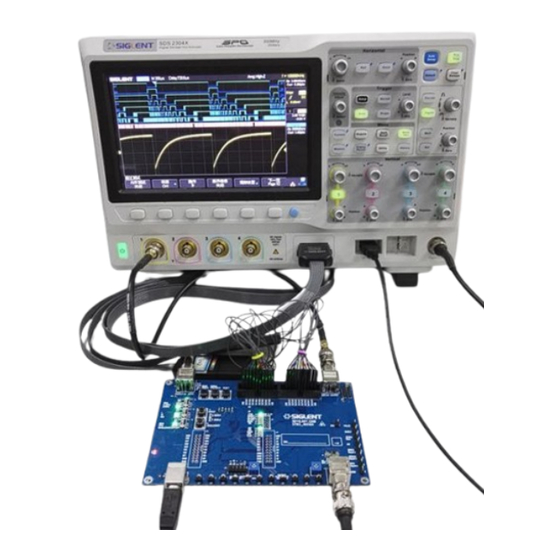
Page 23: Quick Start
Quick Start Connection Example Figure 38 for Common Waveforms STB3 User Manual... - Page 24 Figure 39 for Special Signals STB3 User Manual...
- Page 25 Figure 40 for Serial Protocol Signal STB3 User Manual...
- Page 26 Figure 41 for PASS/FAIL Demonstration STB3 User Manual...
- Page 27 Figure 42 for MSO Demonstration STB3 User Manual...
- Page 28 This page intentionally left blank...
Need help?
Do you have a question about the STB3 and is the answer not in the manual?
Questions and answers