
Summary of Contents for Water Powered Technologies Papa Pump
- Page 1 a great UK design Owner’s Manual Installation, Operation and Maintenance Guide patented design patented design...
-
Page 2: Table Of Contents
Index page no. description Kit contents About the Papa pump Papa technology How the Papa pump works Installation principles Catchment tank details & installations Supply tank details and installation Pump chamber details and installation Multiple installations Reference charts Seradisc filter Installation &... -
Page 3: Kit Contents
Kit Contents exhaust adaptor exhaust adaptor pump pump hose assembly c spanner c spanner Seradisc filters pressure vessel spare set valves 2” ball valve... -
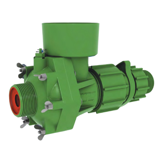
Page 4: About The Papa Pump
Simple water power By utilising a naturally flowing water source, the Papa pump is able to transport up to 30% of that water to the desired location, allowing the residual water to be returned to the natural source. With minimal maintenance and zero fuel costs... -
Page 5: Papa Technology
Papa technology exhaust port adjuster delivery supply port port non-return main valve valve... -
Page 6: How The Papa Pump Works
How the Papa pump works Water enters pump via supply port and flows around main valve to exhaust port. As the flow increases around the main valve a differential pressure occurs causing the valve to suddenly close. The flow and mass of water is then directed through the non-return valve and into the delivery port at a higher pulsed pressure. -
Page 7: Installation Principles
Installation principles A natural water source is required river stream spring pond/lake... - Page 8 Plan Elevation water source flow pump chamber catchment tank supply tank Side Elevation Delivery Head storage tank catchment supply tank pump tank chamber Supply Head The greater the supply head, the more efficient the pump is! MORE SUPPLY HEAD = MORE WATER!
- Page 9 Site Layout Overview storage tank feed pipe feed pipe delivery pipe catchment tank supply tank pump chamber supply pipe overflow pipe A minimum Supply Head of 2 metres is required, but please ensure that the maximum head is achieved for best results Supply Head greater than 2 metres MORE SUPPLY HEAD = MORE WATER!
- Page 10 Supply Head Supply Pipe length L = 4-7 x SH NOTE! The PAPA pump can operate outside of these parameters but the performance will be affected The maximum Delivery Head (DH) is 30 x the Supply Head (SH) Supply Head...
-
Page 11: Catchment Tank Details & Installations
Feed Pipe should be straight with a low gradient (1:500) into the Supply Tank, check pipe friction chart to establish the most suitable size and gradient. feed pipe catchment supply tank tank Catchment Tank details & installations Catchment method 1 1 metre 90 deg bend facing downstream... - Page 12 Catchment method 2 water ingress through stones used as holes drilled in tank coarse filter feed pipe Catchment tank inlet from water source feed pipe Seradisc filters NOTE! The more Seradisc filters fitted, the better the reliability of the system...
- Page 13 Feed Pipe 100mm Feed Pipe NOTE! Larger diameter pipe may be required for multiple pump installations with more than 2 pumps. Please refer to friction chart. Add more Seradisc filters accordingly Overflow Pipe 4” Overflow Pipe NOTE! Larger diameter pipe may be required for multiple pump installations with more than 2 pumps.
-
Page 14: Seradisc Filter
Supply Tank details & installations Supply Tank feed pipe 1 metre Seradisc filter supply pipe overflow pipe 1 metre removable stand pipe (used for draining down) socket Supply Pipe -1 2” (50mm) supply pipe Galvanised steel or MDPE (see next page) - Page 15 Supply Pipe - 2 IF DELIVERY HEAD (DH) IF DELIVERY HEAD (DH) IS LESS THAN 15m IS MORE THAN 15m use 100% Galvanised steel either use do not use 100% MDPE MDPE supply pipe length min 1/3 supply pipe length galvanised into pump Pump Chamber details &...
- Page 16 Pump Chamber Note: Chamber requires a cover if a Sureflow flow valve is fitted nr valve ball valve delivery pipe supply pipe overflow pipe tank drain pump support NOTE! 2 pumps can be installed in a 1m diameter ring. Larger rings will be required for additional pumps Delivery Pipe 25mm delivery...
- Page 17 Multiple pump installations Typical dual pump installation delivery pipe support pumps feed pipes NOTE! Please check delivery pipe size by referring to the pipe friction chart when using multiple pumps or pumping over long distances. Manifolded multiple pump installation NR valve delivery pipe delivery...
- Page 18 Pump performance chart...
- Page 19 seradis Installation methods and performance details cut 2 ¼” dia. holes in pipe and screw in filters use flexible coupling supplied with filter NOTE! The more Seradisc filters fitted, the better the reliability of the system...
- Page 20 Flow through standard 16-disc filters in parallel configuration 1800 1600 1400 1200 1000 no. of filters in parallel filters in parallelf ilters in series Flow through filter and particulate screening flow particulate size no. of discs in filter assembly Note: Particulate sizes are calculated.
-
Page 21: Installation & Commissioning
Installation & commissioning Delivery Pipework, Tanks and Troughs The Delivery pipe should be sized to keep frictional losses to a minimum. A stop valve should be installed at the pump end to allow maintenance and replacement of non return valves etc. without having to drain the whole delivery pipe work. - Page 22 1. Using PTFE tape, screw the 2” BSP adaptor into the 2” lever supply valve. 2. Screw the Papa pump into the adaptor until hand tight and adjust the adaptor so that the pump is in the correct position ie with the exhaust facing upwards.
- Page 23 3. Support the underside of the pump with a suitable wooden block to alleviate the weight on the lever valve. 4. Unscrew the release coupling on the hose assembly and attach the assembly to the pump, ensuring that the rubber valves in the pump are present and correctly installed and that the securing tape has been removed.
- Page 24 6. Adjust the air pressure in the pressure vessel to 0.5bar below the delivery head pressure (10m head = 1bar), e.g. with a delivery head of 50m, the air pressure will be set to 4.5bar. Using PTFE tape, install the pressure vessel into the delivery tee. DH(bar) - 0.5bar 10m=1bar...
- Page 25 Priming and adjustment 1. Turn the adjuster in the direction (+) to open the pump main valve fully. The ‘C’ spanner can be used to assist if required. Adjuster 2. Open the supply lever valve so that water is allowed to flow through the pump and expel any air.
- Page 26 In extreme cases it may be preferable to first prime the whole system using a separate powered pump or pressurised water source to back-fill all the pipe work via the Papa pump exhaust port, although with time and patience priming can always be achieved using the described method.)
- Page 27 Adjuster 5. Check the delivery of the pump at the highest point using a measuring jug. Remember that depending on the delivery pipe length, it can take a long while for the system to fill. You can also check the performance of the pump by fitting a pressure gauge.
-
Page 28: Pump Parts List
Pump parts list 5. Locknut 4. Adjuster 3. Barrel 6. Adaptor 12. O ring 13. Coach bolt x 6 10. Exhaust insert 9. Pressure relief valve 11. Main valve 8. NR Valve x 3 1. Body 14. Body O ring 2. -
Page 29: Pump Maintenance
Pump maintenance How to change the pump valves Changing the valves (8) & (11) is a straightforward procedure and can easily be carried out in the field if required. Firstly shut off the water supply to the pump via the supply lever valve. You can now slowly unscrew and separate the coupling (located after the tee) to release pressure. - Page 30 Using the C spanner, unscrew and remove the hose assembly adaptor and wing nuts. Separate the cone from the body Remove NR valves, noting orientation. Inspect and replace any worn or damaged valves. Slacken the locknut, then turn the adjuster toward the ‘+’. This moves the barrel and main valve forward, allowing easy access to the main valve for removal.
- Page 31 Remove main valve using C spanner, noting orientation. Inspect for wear or damage and replace if necessary. Clean the mating faces of the Body and Cone Refit the wing nuts and first tighten by hand. Then, using the C spanner, tighten each wing nut further by turning 90°...
- Page 32 Reassemble the pump to the supply lever valve and the hose assembly coupling. Refit the pressure vessel and the exhaust insert and follow the steps shown in the section “Installing the Papa pump” in the “Installation & commissioning” instructions to restart the pump.
-
Page 33: Troubleshooting
Troubleshooting Most likely causes, relating to system faults Legend: water pipes airb lockage technical Fault Common causes Action refer to ‘Priming & adjustment’ p.25 Pump beats once, Low delivery pressure then stops... - Page 34 Fault Common causes Action refer to ‘Priming & adjustment’ p.25 Air in supply pipe check water source level ok Pump beats, but stops after a period of time Low water level clean pipes and filters refer to ‘Priming & adjustment’ p.25 Air or blockage in supply pipe or pump...
- Page 35 Fault Common causes Action refer to ‘Priming & adjustment’ p.25 Air in supply pipe Check: refer to Supply Supply pipe length = 4 - 7 x pipe supply head requirements p.10 Irregular beat Check air pressure adjust air pressure if req’d see p24 replace pressure water escapes from...
- Page 36 Fault Common causes Action Check air pressure adjust air pressure if req’d see p24 replace water escapes from pressure valve when depressed vessel replace pressure relief valve pressure relief valve pressure relief valve damaged/worn leaking Check: Delivery Head > 100m Delivery Head <...
-
Page 37: Specifications
Specifications: High Pump housing: Latigloss ® Performance Thermoplastics Valve members/O rings: EPDM Exhaust insert Polypropylene Max output (l/day): 20,000 Max operating pressure (bar): Weight (kg): Length (cm): Width (cm): Height (cm): Supply/exhaust ports: 2” BSP (50mm nb) Delivery port: 1” BSP (25mm nb) - Page 38 Notes...
- Page 39 Notes...
- Page 40 Water Powered Technologies Ltd 14A Kingshill Industrial Estate, Bude, Cornwall, EX23 8QN, UK +44 (0)1288 354454 info@wptglobal.net www.waterpoweredtechnologies.com waterpoweredtek water powered technologies © Water Powered Technologies Ltd. 2016...
Need help?
Do you have a question about the Papa Pump and is the answer not in the manual?
Questions and answers