Table of Contents
Advertisement
Advertisement
Table of Contents

Related Manuals for MSI MS-98E3


Summary of Contents for MSI MS-98E3
- Page 1 MS-98E3 v1.0 Industrial Computer Board...
-
Page 2: Trademarks
▍ Preface Copyright Notice The material in this document is our intellectual property. We take every care in the preparation of this document, but no guarantee is given as to the correctness of its contents. Our products are under continual improvement and we reserve the right to make changes without notice. -
Page 3: Safety Instructions
MS-98E3 Safety Instructions ■ Always read the safety instructions carefully. ■ Keep this User’s Manual for future reference. ■ Keep this equipment away from humidity. ■ Lay this equipment on a reliable flat surface before setting it up. ■ The openings on the enclosure are for air convection hence protects the equipment from overheating. -
Page 4: Ce Conformity
▍ Preface CE Conformity Hereby, we declare that this device is in compliance with the essential safety requirements and other relevant provisions set out in the Euro- pean Directive. FCC-A Radio Frequency Interference Statement This equipment has been tested and found to comply with the limits for a Class A digital device, pursuant to Part 15 of the FCC Rules. -
Page 5: Weee (Waste Electrical And Electronic Equipment) Statement
MS-98E3 WEEE ( ) Statement Waste Electrical and Electronic Equipment ENGLISH Under the European Union (“EU”) Directive on Waste Electrical and Elec- tronic Equipment, Directive 2002/96/EC, which takes effect on August 13, 2005, products of “electrical and electronic equipment” cannot be discard-... - Page 6 ▍ Preface meer beschouwd worden als vervuiling. Fabrikanten van dit soort producten worden verpli- cht om producten retour te nemen aan het eind van hun levenscyclus. SRPSKI Po Direktivi Evropske unije (“EU”) o odbačenoj ekektronskoj i električnoj opremi, Direktiva 2002/96/EC, koja stupa na snagu od 13. Avgusta 2005, proizvodi koji spadaju pod “elek- tronsku i električnu opremu”...
-
Page 7: Table Of Contents
MS-98E3 ▍ CONTENTS Copyright Notice �������������������������������������������������������������������������������������������������� ii Trademarks ���������������������������������������������������������������������������������������������������������� ii Revision History �������������������������������������������������������������������������������������������������� ii Technical Support ����������������������������������������������������������������������������������������������� ii Safety Instructions ��������������������������������������������������������������������������������������������� iii CE Conformity ���������������������������������������������������������������������������������������������������� iv FCC-A Radio Frequency Interference Statement �������������������������������������������� iv WEEE (Waste Electrical and Electronic Equipment) Statement ��������������������� v Chapter 1 Overview ������������������������������������������������������������������������������������������... - Page 8 NOTE...
-
Page 9: Chapter 1 Overview
Chapter 1 Overview Thank you for choosing the MS-98E3, the excellent industrial computer boards. Based on the innovative Intel Bay Trail processor ® for optimal system efficiency, and supports 2 DDR3L 1066/1333 SO-DIMM slots to provide the maximum of 8GB memory capacity. -
Page 10: Mainboard Specifications
▍ Overview Mainboard SpecificationS Processor ■ Intel Dual or Quad-core Bay Trail ® Memory ■ 2 unbuffered non-ECC DDR3L 1066/ 1333 SO-DIMM slots ■ Supports the maximum capacity of 8GB ■ Intel WGI210AT GbE controller ® ■ Audio Realtek ALC887 Codec ®... - Page 11 MS-98E3 Onboard ■ Onboard Connectors/Pinheaders 1 SATA 3Gb/s port Connectors/ 2 USB 2.0 pinheader (for 4 ports) Pinheaders 1 USB 3.0 pinheader (for 1 ports) 1 PS2 pinheader 1 GPIO connector 4 Serial port connectors 1 Front Panel pinheader 1 CPU Fan pinheader...
-
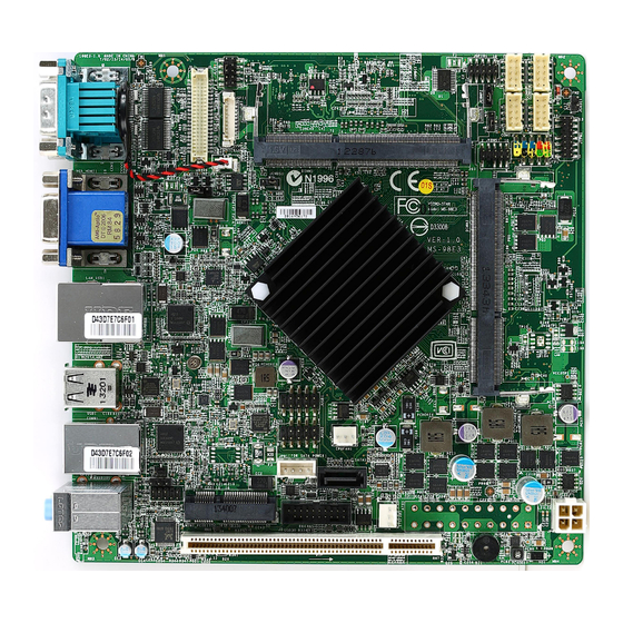
Page 12: Layout
▍ Overview Layout JLCD GPIO SO-DIMM COM3~6 Jumper Connector Slot Port COM Port JLVDS JSPI1 Connector Power AT/ ATX Connector Connector Jumper Jumper Chassis Intrusion Connector JTPM1 Connector Front Panel Connector JKBMS1 Connector JCMOS1 Jumper SO-DIMM Slot JLAN1 Jumper USB 2.0 Connector CPU Fan Connector... -
Page 13: Chapter 2 Hardware Setup
Chapter 2 Hardware Setup This chapter provides you with the information on mainboard hardware configurations. Incorrect setting of jumpers and connectors may damage your main- board. Please pay special attention not to connect these headers in wrong direction. DO NOT adjust any jumper while the mainboard is powered on. -
Page 14: Memory
▍ Hardware Setup Memory The SO-DIMM slot is intended for memory modules. 1. Locate the SO-DIMM slot. Align the notch on the DIMM with the key on the slot and insert the DIMM into the slot. 2. Push the DIMM gently downwards until the slot levers click and lock the DIMM in place. -
Page 15: Power Supply
MS-98E3 power Supply 20-Pin Power Connector: ATX1 (optional by model) This connector allows you to connect to an ATX power supply. To connect to the ATX power supply, make sure the plug of the power supply is in- serted in the proper orientation and the pins are aligned. Then push down the power supply firmly into the connector. -
Page 16: Back Panel I/O
▍ Hardware Setup back paneL i/o Port VGA Port Line-In Port Line-Out USB 2.0 Serial HDMI Port Ports Ports ▶ VGa port The DB15-pin female connector is provided for monitor. ▶ uSb 2.0 port The USB (Universal Serial Bus) port is for attaching USB devices such as keyboard, mouse, or other USB-compatible devices. - Page 17 MS-98E3 ▶ Serial Port Connector: COM1/ COM2 The serial port is a 16550A high speed communications port that sends/ receives 16 bytes FIFOs. You can attach a serial mouse or other serial devices directly to the connector. COM1 supports RS-232/422/485.
- Page 18 ▍ Hardware Setup ▶ audio ports These audio connectors are used for audio devices. It is easy to differenti- ate between audio effects according to the color of audio jacks. ■ Line-in (blue) - Line in, is used for external cd player, tapeplayer or other audio devices.
-
Page 19: Connector
MS-98E3 connector Serial ATA Connector: SATA1 This connector is a high-speed Serial ATA interface port. Each connector can connect to one Serial ATA device. Important Please do not fold the Serial ATA cable into 90-degree angle. Otherwise, data loss may occur during transmission. - Page 20 ▍ Hardware Setup Fan Power Connector: CPUFAN1 / SYSFAN1 The fan power connectors support system cooling fan with +12V. When connecting the wire to the connectors, always note that the red wire is the positive and should be connected to the +12V; the black wire is Ground and should be connected to GND.
- Page 21 MS-98E3 S/PDIF-Out Pinheader: JSPDI1 This connector is used to connect S/PDIF (Sony & Philips Digital Intercon- nect Format) interface for digital audio transmission. TPM Module Connector: JTPM1 This connector can be used as a debug port. GPIO Connector: JGPIO1 This connector is provided for the General-Purpose Input/Output (GPIO)
- Page 22 ▍ Hardware Setup Front USB Connector: JUSB1/ JUSB2 This connector, compliant with Intel I/O Connectivity Design Guide, is ideal for connecting high-speed USB interface peripherals such as USB HDD, digital cameras, MP3 players, printers, modems and the like. Important Note that the pins of VCC and GND must be connected correctly to avoid possible damage.
- Page 23 MS-98E3 Chassis Intrusion Switch Connector: JCASEI1 This connector connects to the chassis intrusion switch cable. If the chas- sis is opened, the chassis intrusion mechanism will be activated. The sys- tem will record this status and show a warning message on the screen. To clear the warning, you must enter the BIOS utility and clear the record.
- Page 24 ▍ Hardware Setup Serial Port Connector: COM3~6 These connectors are 16550A high speed communications port that sends/receives 16 bytes FIFOs. LVDS Connector: JLVDS1 The LVDS (Low Voltage Differential Signal) connector provides a digital interface typically used with flat panels. After connecting an LVDS inter- face flat panel to the JLVDS1, be sure to check the panel datasheet and set the JLCD jumper to proper power voltage.
-
Page 25: Jumper
MS-98E3 JuMper Clear CMOS Jumper: JCMOS1 There is a CMOS RAM onboard that has a power supply from an external battery to keep the data of system configuration. With the CMOS RAM, the system can automatically boot OS every time it is turned on. If you want to clear the system configuration, set the jumper to clear data. - Page 26 ▍ Hardware Setup LVDS Power Jumper: JLCD1 The LVDS power jumper allows users to select the operation voltage of the LVDS flat panel. JLCD1 Important Avoid adjusting the jumper when the system is on; it will damage the board. COM Port Power Jumper: JCOMP1/ JCOMP2 These jumpers specify the operation voltage of the onboard serial ports.
-
Page 27: Slot
MS-98E3 SLot PCI (Peripheral Component Interconnect) Slot The PCI slot supports LAN card, SCSI card, USB card, and other add-on cards that comply with PCI specifications. 32-bit pci Slot Important When adding or removing expansion cards, make sure that you unplug the power supply first. - Page 28 NOTE...
-
Page 29: Chapter 3 Bios Setup
Chapter 3 BIOS Setup This chapter provides information on the BIOS Setup program and allows you to configure the system for optimum use. You may need to run the Setup program when: ■ An error message appears on the screen during the system booting up, and requests you to run SETUP. -
Page 30: Entering Setup
▍ BIOS Setup Entering Setup Power on the computer and the system will start POST (Power On Self Test) process. When the message below appears on the screen, press <DEL> or <F2> key to enter Setup. PRESS DEL OR F2 TO ENTER SETUP If the message disappears before you respond and you still wish to enter Setup, restart the system by turning it OFF and On or pressing the RESET button. - Page 31 MS-98E3 CoNtRol KEYS ← → Select Screen ↑ ↓ Select Item Enter Select Change Option General Help Previous Values Optimized Defaults Save & Exit Exit GETTING HELP After entering the Setup menu, the first menu you will see is the Main Menu.
-
Page 32: The Menu Bar
▍ BIOS Setup The Menu Bar ▶ Main Use this menu for basic system configurations, such as time, date, etc. ▶ Advanced Use this menu to set up the items of special enhanced features. ▶ Boot Use this menu to specify the priority of boot devices. ▶... - Page 33 MS-98E3 Main ▶ System Date This setting allows you to set the system date. The date format is <Day>, <Month> <Date> <Year>. ▶ System Time This setting allows you to set the system time. The time format is <Hour> <Minute> <Second>.
- Page 34 ▍ BIOS Setup Advanced ▶ Bootup NumLock State This setting is to set the Num Lock status when the system is powered on. Setting to [On] will turn on the Num Lock key when the system is powered on. Setting to [Off] will allow users to use the arrow keys on the numeric keypad.
- Page 35 MS-98E3 ▶ Super IO Configuration ▶ Serial Port 1/ 2/ 3/ 4/ 5/ 6 This setting enables/disables the specified serial port. ▶ Change Settings This setting is used to change the address & IRQ settings of the specified serial port.
- Page 36 ▍ BIOS Setup ▶ Smart Fan Configuration ▶ Smart FAN1/ Smart FAN2 Function These settings enable/disable the Smart Fan function. Smart Fan is an excellent feature which will adjust the CPU/system fan speed automati- cally depending on the current CPU/system temperature, avoiding the overheating to damage your system.
- Page 37 MS-98E3 ▶ EIST EIST (Enhanced Intel SpeedStep Technology) allows the system to dynamically adjust processor voltage and core frequency, which can result in decreased average power consumption and decreased average heat production. When disabled, the processor will return the actual maximum CPUID input value of the processor when queried.
- Page 38 ▍ BIOS Setup ▶ GPIO Group Configuration ▶ GPO 0~3 These settings control the operation mode of the specified GPIO. 3-10...
- Page 39 MS-98E3 Boot ▶ CSM Support This setting allows users to set the device to enable/ disable the legacy BIOS ROM boot. ▶ Boot Option Priorities This setting allows users to set the sequence of boot devices where BIOS attempts to load the disk operating system.
- Page 40 ▍ BIOS Setup Security ▶ Administrator Password Administrator Password controls access to the BIOS Setup utility. ▶ User Password User Password controls access to the system at boot and to the BIOS Setup utility. ▶ Chassis Intrusion The fieldenables or disables the feature of recording the chassis intrusion status and issuing a warning message if the chassis is once opened.
- Page 41 MS-98E3 ▶ Console Redirection Settings ▶ Terminal Type To operate the system’s console redirection, you need a terminal supporting ANSI terminal protocol and a RS-232 null modem cable connected between the host system and terminal(s). This setting specifies the type of terminal device for console redirection.
- Page 42 ▍ BIOS Setup ▶ Redirection After BIOS POST This item specifies whether or not the console redirection is run after the Power-On Self Test (POST). [Always] Redirection is always active. (Some operating systems may not work if this item is set to Always.) [Boot Loader] Redirection is only active during POST.
- Page 43 MS-98E3 Intel Anti-Theft Technology ▶ Intel AT This setting enables/disables Intel Anti-Theft Technology. ▶ Intel AT Platform PBA This setting enables/disables the Pre-Boot Authentication of Intel Anti- Theft Technology. ▶ Intel AT Platform Suspend Mode This setting enables/disables the platform suspend mode of Intel Anti- Theft Technology.
- Page 44 ▍ BIOS Setup Chipset ▶ Integrated Graphics Device This setting enables/disables the Integrated Graphics chipset. ▶ DVMT Pre-Allocated This setting defines the DVMT pre-allocated memory. Pre-allocated memory is the small amount of system memory made available at boot time by the system BIOS for video. Pre-allocated memory is also known as locked memory.
- Page 45 MS-98E3 Power ▶ Restore AC Power Loss This setting specifies whether your system will reboot after a power failure or interrupt occurs. Available settings are: [Power Off] Leaves the computer in the power off state. [Power On] Leaves the computer in the power on state.
- Page 46 ▍ BIOS Setup Advanced Resume Events Control ▶ PCIE/PCI PME This field specifies whether the system will be awakened from power saving modes when activity or input signal of onboard PCIE/ PCI PME is detected. ▶ USB from S3/S4 The item allows the activity of the USB device to wake up the system from S3/S4 sleep state.
-
Page 47: Save & Exit Menu
MS-98E3 Save & Exit ▶ Discard Changes and Exit Abandon all changes and exit the Setup Utility. ▶ Save Changes and Reset Save changes to CMOS and reset the system. ▶ Discard Changes Abandon all changes. ▶ Restore Defaults Use this menu to load the default values set by the mainboard manufacturer specifically for optimal performance of the mainboard. -
Page 48: Chapter 4 System Resources
Chapter 4 System Resources This chapter provides information on system re- sources. -
Page 49: Gpio Sample Code
▍ System Resources GPIO sample code GPI 0 ~ GPI 3 GPI 0 GPI 1 GPI 2 GPI 3 IO Address SIO GPIO Register Sample code GPO 0 ~ GPO 3 GPO 0 GPO 1 GPO 2 GPO 3 IO Address SIO GPIO Register Sample code... - Page 50 98E3 short $+2 ;Io_delay dx, al ; Sitch GPIO oniguration or SIO LDN 0x0 dx, SIO_INDEX_Port al, 07h dx, al dx, SIO_DATA_Port al, SIO_LDN_GPIO dx, al ; Get GPI 0 Pin Status Register dx, SIO_INDEX_Port al, GPI_REG dx, al dx, SIO_DATA_Port al, dx ;al bit0 = GPI 0 status Exit SIO...
-
Page 51: Watch Dog Timer Sample Code
▍ System Resources Watch Dog Timer Sample Code SIO_INDEX_Port equ 04Eh SIO_DATA_Port equ 04Fh SIO_UnLock_Value equ 087h SIO_Lock_Value equ 0AAh WatchDog_LDN equ 007h WDT_UNIT equ 60h ;60h=second, 68h=minute, 40h=Disabled Watchdog timer WDT_Timer equ 30 ;ex. 30 seconds Sample code: ;Enable config mode dx, SIO_INDEX_Port al, SIO_UnLock_Value dx, al...
Need help?
Do you have a question about the MS-98E3 and is the answer not in the manual?
Questions and answers