Sign In
Upload
Download
Table of Contents
Contents
Add to my manuals
Delete from my manuals
Share
URL of this page:
HTML Link:
Bookmark this page
Add
Manual will be automatically added to "My Manuals"
Print this page
×
Bookmark added
×
Added to my manuals
Manuals
Brands
Xovis Manuals
Accessories
PC Series
User manual
Xovis PC Series User Manual
Hide thumbs
Also See for PC Series
:
User manual
(100 pages)
1
2
3
4
5
6
7
8
9
10
11
12
13
14
15
16
17
18
19
20
21
22
23
24
25
26
27
28
29
30
31
32
33
34
35
36
37
38
39
40
41
42
43
44
45
46
47
48
49
50
51
52
53
54
55
56
57
58
59
60
61
62
63
64
65
66
67
68
69
70
71
72
73
74
75
76
77
78
79
80
81
82
83
84
85
86
87
88
89
90
91
92
93
94
95
96
97
98
99
Table Of Contents
100
page
of
100
Go
/
100
Contents
Table of Contents
Troubleshooting
Bookmarks
Table of Contents
Document History
Table of Contents
1 Overview
Content Declaration
PC-Series Hardware Concept
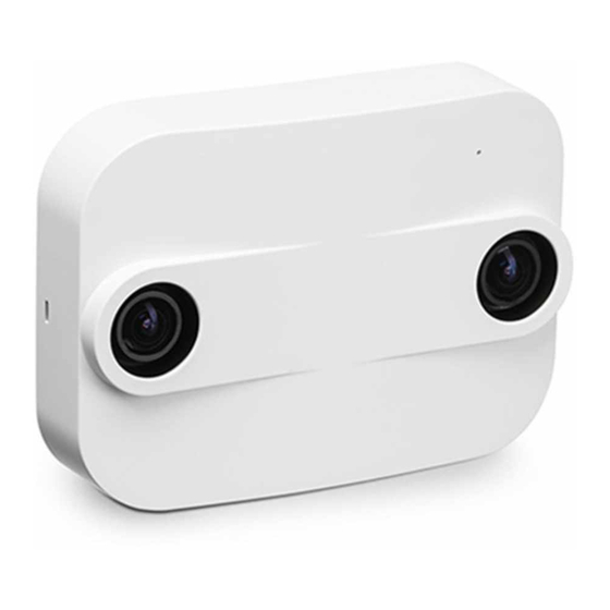
PC-Series 3D Sensor
2 Installation Fundamentals
Network Requirements
Power over Ethernet
Sensor LED
3 Configuration & Usage
Person Tracking
Person Generation
Demonstration of Person Generation with Coordinate Mode “Head”
Person Position / Coordinate Mode
Different Tracking Areas Depending on the Coordinate Mode
Introduction
Setting up the Sensor in the Network
Xovis Sensor Explorer
Discover Sensor on the Network
Found Sensors on the Network
Installing a Sensor in a Fix IP Environment
Set Fix IP Menu Item
Set Fix-IP Dialog
Setting a Fix IP Address to a Discovered Sensor
Set Fix-IP
Upgrading a Sensor
Multi Upgrade
Access the Web Interface
Https
Supported Browsers
Login to the Sensor
Navigation
Login Screen
Plugins
Plugin Button in the Navigation Bar
Setup Wizard
Welcome Screen
Network Settings & Identification
Date & Time
Sensor Settings I
Sensor Settings II
Mark the Scene Floor
Drawn Scene Floor
Name a Scene Item
Floor Mask in Different Scene Situations
Re-Calibrate Sensor
Validate the Person Size
Setup the Counting Items
Coordinate Mode
Detect Height
Scene View Controls
Bubble Displayed on Tracked Person
Displayed Path of Tracked Person
Pathmap Helps to Identify the Actual Tracking While Setting up the Counting Elements
Start/Stop Map Visualizes Generation and Deletion Points of Persons
Count Lines
Orientation of a Count Line
Count Zone
A Multi-Point Line
Scene Elements
Highlighted Scene Element
Show / Hide a Scene Element
Delete a Scene Element
Switch Count Line Orientation
Count Item Configuration
Count Line Configuration
Open Count Item Configuration
Line Name
Count Mode
Activation Zone
Deactivation Zone
Example Situations
Minimum Height
Maximum Height
Count Zone Configuration
Zone Name
Zone Data Persistence & Dwell Time
Privacy Mode
Finishing the Wizard
Live View
Scene Live View
Live Count States
24H Live Statistics
Validation Recording
Schedule a Recording
Manage Recordings
Multisensor Validation Recording
Analytics View
Persisted Count Data
Warning of too Many Data Points
Count Zone Charts
Occupancy
Dwell Time Statistics
Dwell Time Distribution
Visualization Maps
Multisensor Visualization Maps
Config View
Control Buttons
Save
Discard Changes
Configuration Save Indicator
Start Setup Wizard
Reboot
Export/Import
Scene View
Settings
Sensor
Data Push
Example Configuration for Pushing Count Data to Remote Destination
Example Configuration for Pushing Validation Recordings to Remote Destination
Person Coordinates
Users
Disabled Config View When Logged in with User Account
User Account Enabled
System
Network
Multisensor
Status View
Info
Data Retention
Version
Connectivity
Firmware Upgrade
Extended Analytics
Configuration Changes from Another Client
Connection Warning
4 Troubleshooting
False Behavior
Exclusion Masks
Taboo Masks
Exclusion Mask on Mirroring Wall and Information Column
Taboo Mask for Marking the Scene Boundary
Taboo Mask on Unstructured White Wall and Marking the Scene Boundary over Two Doors
Taboo Mask on a Sign Within the Sensor View
Example for Mask Differentiation
Placement of Dwell Zones
Illustration of Different Tracks and Their Influence on Dwell Time Calculation
Time Synchronization Mechanism
5 Technical Data
6 Certificates / Tests
7 Custom Integration
Api
Plugin Architecture
Advertisement
Quick Links
1
Installation Fundamentals
Download this manual
PC-Series
User manual
Table of
Contents
Previous
Page
Next
Page
1
2
3
4
5
Advertisement
Table of Contents
Need help?
Do you have a question about the PC Series and is the answer not in the manual?
Ask a question
Questions and answers
Related Manuals for Xovis PC Series
Security Sensors Xovis PC2S User Manual
(100 pages)
Accessories Xovis PC2 User Manual
(100 pages)
Accessories Xovis PC3 User Manual
(100 pages)
This manual is also suitable for:
Pc2
Pc3
Table of Contents
Save PDF
Print
Rename the bookmark
Delete bookmark?
Delete from my manuals?
Login
Sign In
OR
Sign in with Facebook
Sign in with Google
Upload manual
Upload from disk
Upload from URL


Need help?
Do you have a question about the PC Series and is the answer not in the manual?
Questions and answers