Bryant 582A Series Installation, Start-Up And Service Instructions Manual
Single package gas heating/ electric cooling units
Hide thumbs
Also See for 582A Series:
- User's information manual (8 pages) ,
- User manual (25 pages) ,
- Installation, start-up, and operating instructions manual (36 pages)
Table of Contents
Advertisement
CONTENTS
SAFETY CONSIDERATIONS . . . . . . . . . . . . . . . . . . . . . . . . 1
GENERAL . . . . . . . . . . . . . . . . . . . . . . . . . . . . . . . . . . . . . . 1-3
RECEIVING AND INSTALLATION . . . . . . . . . . . . . . . . . 4-14
I. Step 1 - Check Equipment . . . . . . . . . . . . . . . . . . 4
II. Step 2 - Provide Unit Support . . . . . . . . . . . . . . . 4
III. Step 3 - Field Fabricate Ductwork . . . . . . . . . . . . 4
IV. Step 4 - Provide Clearances . . . . . . . . . . . . . . . . . 4
V. Step 5 - Rig and Place Unit . . . . . . . . . . . . . . . . . 4
VI. Step 6 - Connect Condensate Drain . . . . . . . . . . 7
VII. Step 7 - Install Flue Hood . . . . . . . . . . . . . . . . . . . 7
VIII. Step 8 - Install Gas Piping . . . . . . . . . . . . . . . . . . 7
IX. Step 9 - Install Duct Connections . . . . . . . . . . . 10
X. Step 10 - Install Electrical Connections . . . . . . 11
PRE-START-UP . . . . . . . . . . . . . . . . . . . . . . . . . . . . . . . . 14,15
START-UP . . . . . . . . . . . . . . . . . . . . . . . . . . . . . . . . . . . . 15-29
I. Check for Refrigerant Leaks . . . . . . . . . . . . . . . . . 15
Make Adjustments . . . . . . . . . . . . . . . . . . . . . . . . . 15
Make Adjustments . . . . . . . . . . . . . . . . . . . . . . . . . 18
MAINTENANCE . . . . . . . . . . . . . . . . . . . . . . . . . . . . . . . . 29-32
I. Air Filter . . . . . . . . . . . . . . . . . . . . . . . . . . . . . . . . . . 30
II. Evaporator Blower and Motor . . . . . . . . . . . . . . . . 30
III. Flue Gas Passageways . . . . . . . . . . . . . . . . . . . . . 30
IV. Combustion-Air Blower . . . . . . . . . . . . . . . . . . . . . 30
V. Limit Switch . . . . . . . . . . . . . . . . . . . . . . . . . . . . . . 30
VI. Burner Ignition . . . . . . . . . . . . . . . . . . . . . . . . . . . . 31
VII. Main Burners . . . . . . . . . . . . . . . . . . . . . . . . . . . . . 31
IX. Condenser Fan . . . . . . . . . . . . . . . . . . . . . . . . . . . . 32
X. Electrical Controls and Wiring . . . . . . . . . . . . . . . 32
XI. Refrigerant Circuit . . . . . . . . . . . . . . . . . . . . . . . . . 32
XII. Gas Input . . . . . . . . . . . . . . . . . . . . . . . . . . . . . . . . . 32
XIII. Evaporator Airflow . . . . . . . . . . . . . . . . . . . . . . . . . 32
XIV. Metering Device - Acutrol™ Device . . . . . . . . . . 32
XV. Liquid Line Strainer . . . . . . . . . . . . . . . . . . . . . . . . 32
TROUBLESHOOTING . . . . . . . . . . . . . . . . . . . . . . . . . . . 33-35
START-UP CHECKLIST . . . . . . . . . . . . . . . . . . . . . . . . . . CL-1
NOTE TO INSTALLER - Before the installation, READ THESE
INSTRUCTIONS CAREFULLY AND COMPLETELY. Also,
make sure the User's Manual and Replacement Guide are
left with the unit after installation. The furnace is NOT to be
used for temporary heating of buildings or structures under
construction.
SAFETY CONSIDERATIONS
Installation and servicing of air-conditioning equipment can
be hazardous due to system pressure and electrical compo-
nents. Only trained and qualified personnel should install,
repair, or service air-conditioning equipment.
Untrained personnel can perform basic maintenance func-
tions of cleaning coils and filters. All other operations should
installation, start-up
and service instructions
SINGLE PACKAGE GAS HEATING/
ELECTRIC COOLING UNITS
Page
Cancels: II 582A-18-1
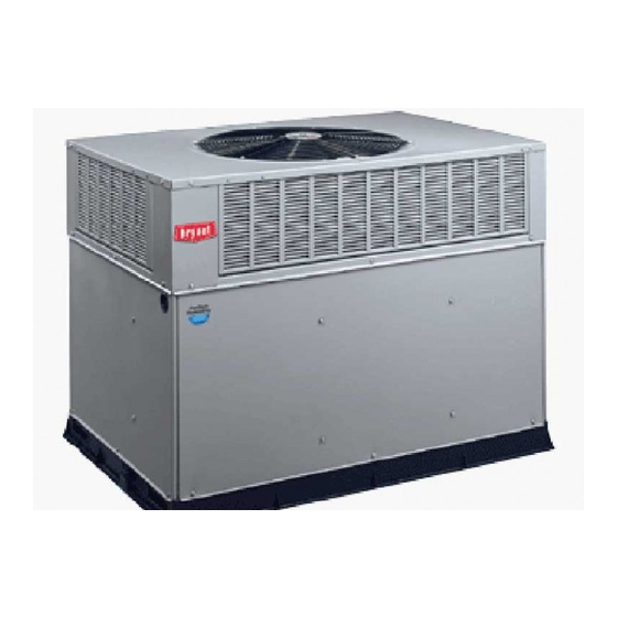
Fig. 1 - Units 582A and 583A
(Shown with Accessory Wire Grille)
be performed by trained service personnel. When working on
air-conditioning equipment, observe precautions in the lit-
erature, tags and labels attached to the unit, and other safety
precautions that may apply.
Follow all safety codes. Wear safety glasses and work gloves.
Use quenching cloth for unbrazing operations. Have fire ex-
tinguisher available for all brazing operations.
WARNING: Improper installation, adjustment, alter-
ation, service, maintenance, or use can cause carbon mon-
oxide poisoning, fire, or an explosion which can result
in personal injury or unit damage. Consult a qualified
installer, service agency, or gas supplier for informa-
tion or assistance. The qualified installer or agency must
use only factory-authorized kits or accessories when modi-
fying this product.
WARNING: Before performing service or mainte-
nance operations on unit, turn off gas supply then unit
main power switch. Electrical shock could cause per-
sonal injury.
GENERAL
The 582A and 583A units (see Fig. 1) are fully self-contained,
combination Category I gas heating/electric cooling units de-
signed for outdoor installation. See Fig. 2 and 3 (pages 2,3)
for unit dimensions. All unit sizes have return and discharge
openings for both horizontal and downflow configurations, and
are factory shipped with all downflow duct openings covered.
Units may be installed on a rooftop, a cement slab, or di-
rectly on the ground (if permitted by local codes). See Fig. 4
for roof curb dimensions.
582A
Sizes 018-060
583A
Sizes 024-060
1
1
⁄
to 5 Nominal Tons
2
II 582A-18-2
3/15/99
Advertisement
Table of Contents

Related Manuals for Bryant 582A Series


Summary of Contents for Bryant 582A Series
-
Page 1: Table Of Contents
installation, start-up 582A Sizes 018-060 and service instructions 583A SINGLE PACKAGE GAS HEATING/ Sizes 024-060 ELECTRIC COOLING UNITS ⁄ to 5 Nominal Tons Cancels: II 582A-18-1 II 582A-18-2 3/15/99 CONTENTS Page SAFETY CONSIDERATIONS ......1 GENERAL . - Page 2 REQ’D CLEARANCES TO COMBUSTIBLE MAT’L. in. (mm) Top of unit ......14 (355.6) Duct side of unit .
- Page 3 REQ’D CLEARANCES FOR OPERATION AND SERVICING. in. (mm) REQ’D CLEARANCES TO COMBUSTIBLE MAT’L. in. (mm) Evaporator coil access side ..... 36 (914) Top of unit .
-
Page 4: Receiving And Installation
Check all items against shipping list. Immediately notify the Gas Association] B149 Installation Codes), or applicable pro- nearest Bryant Air Conditioning office if any item is missing. visions of local building code. To prevent loss or damage, leave all parts in original pack- ages until installation. - Page 5 UNIT SIZE PART NUMBER in. [mm] in. [mm] in. [mm] in. [mm] CPRFCURB006A00 8 [203] ⁄ [301] ⁄ [778] ⁄ [730] 582A018-042 583A024-036 CPRFCURB007A00 14 [356] ⁄ [301] ⁄ [778] ⁄ [730] FLAT CURB CPRFCURB008A00 8 [203] ⁄ [402] ⁄ [1070] ⁄...
- Page 6 Fig. 5 — Slab Mounting Details UNIT MAXIMUM 582A WEIGHT Size 123.2 20.0 508.0 14.0 355.6 137.3 22.5 571.5 13.0 330.2 137.3 21.5 546.1 13.75 349.3 152.7 22.5 571.5 14.0 355.6 171.4 21.5 546.1 13.5 342.9 198.6 22.0 558.5 17.0 432.0 214.5 22.0...
-
Page 7: Step 6 - Connect Condensate Drain
VI. STEP 6 — CONNECT CONDENSATE DRAIN 2. Remove flue hood from shipping location (inside the blower compartment). Place vent cap assembly over flue panel. NOTE: When installing condensate drain connection be sure Orient screw holes in vent cap with holes in the flue panel. to comply with local codes and restrictions. - Page 8 Table 1 — Physical Data — Unit 582A UNIT SIZE 582A 018040 024040 024060 030040 030060 036060 036090 042060 042090 NOMINAL CAPACITY (ton) ⁄ ⁄ ⁄ ⁄ ⁄ OPERATING WEIGHT (lb) COMPRESSORS Reciprocating Quantity REFRIGERANT (R-22) Quantity (lbs) 3.65 3.65 3.75 3.75 REFRIGERANT METERING DEVICE...
- Page 9 Table 2 — Physical Data — Unit 583A UNIT SIZE 583A 024040 024060 030040 030060 036060 036090 042060 042090 NOMINAL CAPACITY (ton) ⁄ ⁄ ⁄ ⁄ OPERATING WEIGHT (lb) COMPRESSORS Scroll Quantity REFRIGERANT (R-22) Quantity (lb) REFRIGERANT METERING DEVICE Orifice ID (in.) .034 .034 .030...
-
Page 10: Step 9 - Install Duct Connections
(Text continued from page 7) 1. Open all electrical disconnects before starting any serv- ice work. 2. Remove return duct cover located on duct panel by break- CAUTION: Unstable operation may occur when the ing connecting tabs with screwdriver and a hammer gas valve and manifold assembly are forced out of po- (Fig. -
Page 11: Step 10 - Install Electrical Connections
Table 3 — Maximum Gas Flow Capacity* NOMINAL LENGTH OF PIPE, FT† INTERNAL IRON PIPE, DIAMETER SIZE (in.) (in.) ⁄ .622 — — ⁄ .824 1.049 ⁄ 1.380 1400 ⁄ 1.610 2100 1460 1180 *Capacity of pipe in cu ft of gas per hr for gas pressure of 0.5 psig or less. Pressure drop of 0.5-in. wg (based on a 0.60 specific gravity gas). - Page 12 Single phase units: 5. Connect field wire L2 to yellow wire on connection 13 of the compressor contactor. 1. Run the high-voltage (L1, L2) and ground leads into the control box. 6. Connect field wire L3 to blue wire from compressor. 2.
- Page 13 Table 5 — Electrical Data — Unit 538A VOLTAGE OUTDOOR FAN INDOOR FAN POWER SUPPLY FUSE OR UNIT COMPRESSOR RANGE MOTOR MOTOR HACR BRKR SIZE V-PH-Hz 583A MOCP* 208/230-1-60 10.3 56.0 15.7 208/230-1-60 13.5 73.0 19.8 208/230-3-60 63.0 14.2 208/230-1-60 16.7 97.0 25.3...
-
Page 14: Pre-Start-Up
PRE-START-UP WARNING: Failure to observe the following warn- HIGH VOLTAGE POWER LEADS ings could result in serious personal injury: POWER (SEE UNIT WIRING SUPPLY LABEL) 1. Follow recognized safety practices and wear protec- tive goggles when checking or servicing refrigerant system. -
Page 15: Check For Refrigerant Leaks
4. Verify the following conditions: II. START UP HEATING SECTION AND MAKE ADJUSTMENTS CAUTION: Do not purge gas supply into the com- bustion chamber. Do not use a match or other open flame CAUTION: Complete the required procedures given to check for gas leaks. Failure to follow this warning in Pre-Start-Up section on page 14 before starting the could result in an explosion causing personal injury or unit. - Page 16 Table 6 — Heating Inputs GAS SUPPLY PRESSURE MANIFOLD HEATING NUMBER (in. wg) PRESSURE INPUT (in. wg) Natural Propane† (Btuh*) ORIFICES Natural Propane† 40,000 13.0 13.0 60,000 13.0 13.0 90,000 13.0 13.0 115,000 13.0 13.0 130,000 13.0 13.0 * When a unit is converted to propane, different size orifices must be used. See separate natural- to-propane conversion kit instructions.
- Page 17 Measure Manifold Pressure (Propane Units) The main burner orifices on a propane gas unit are sized for the unit rated input when the manifold pressure reading matches the level specified in Table 6. Proceed as follows to adjust gas input on a propane gas unit: 1.
-
Page 18: Start Up Cooling Section And Make Adjustments
F. Heating Sequence of Operation III. START UP COOLING SECTION AND MAKE ADJUSTMENTS See Fig. 15-17 and unit wiring label. On a call for heating, terminal ‘‘W’’ of the thermostat is en- ergized, starting the induced-draft motor. When the hall- CAUTION: Complete the required procedures given effect sensor on the induced-draft motor senses that it has in the Pre-Start-Up section on page 14 before starting... - Page 19 LEGEND — Blower Relay — Rollout Switch — Contactor — Thermistor Start — Capacitor TRAN — Transformer COMP — Compressor Motor — Combustion Relay Field Splice EQUIP — Equipment — Fusible Link Terminal (Marked) — Fuse — Ground Terminal (Unmarked) —...
- Page 20 LEGEND — Adjustable Heat Anticipator — National Electrical Code — Blower Relay — Outdoor-Fan Motor — Contactor — Quadruple Terminal — Capacitor — Rollout Switch COMP — Compressor Motor — Sensor — Combustion Relay — Switch — Centrifugal Switch TRAN — Transformer EQUIP —...
- Page 21 LEGEND — Adjustable Heat Anticipator — National Electrical Code — Blower Relay — Outdoor-Fan Motor — Contactor — Quadruple Terminal — Capacitor — Rollout Switch COMP — Compressor Motor — Sensor — Combustion Relay — Switch — Centrifugal Switch TRAN — Transformer EQUIP —...
- Page 22 B. Checking and Adjustment Refrigerant Charge C. Indoor Airflow and Airflow Adjustments The refrigerant system is fully charged with R-22 refriger- ant, tested, and factory-sealed. CAUTION: For cooling operation, the recommended NOTE: Adjustment of the refrigerant charge is not required airflow is 350 to 450 cfm for each 12,000 Btuh of rated unless the unit is suspected of not having the proper R-22 cooling capacity.
- Page 23 Fig. 18 — Cooling Charging Chart, Fig. 20 — Cooling Charging Chart, 582A018 Units 582A030 Units Fig. 19 — Cooling Charging Chart, Fig. 21 — Cooling Charging Chart, 582A024 Units 582A036 Units —23—...
- Page 24 Fig. 21 — Cooling Charging Chart, Fig. 23 — Cooling Charging Chart, 582A042 Units 582A048 Units Fig. 24 — Cooling Charging Chart, 582A060 Units —24—...
- Page 25 Fig. 25 — Cooling Charging Chart, Fig. 27 — Cooling Charging Chart, 583A024 Units 583A036 Units Fig. 28 — Cooling Charging Chart, Fig. 26 — Cooling Charging Chart, 583A042 Units 583A030 Units —25—...
- Page 26 Fig. 29 — Cooling Charging Chart, Fig. 30 — Cooling Charging Chart, 583A048 Units 583A060 Units —26—...
- Page 27 Table 9 — Dry Coil Air Delivery* — Horizontal and Downflow Discharge — Unit 582A018-060 (Deduct 10% for 208 Volts) 230 AND 460 VOLT External Static Pressure (in. wg) Unit Motor 582A Speed Watts — — — — — 1082 1016 —...
- Page 28 Table 10 — Dry Coil Air Delivery* — Horizontal and Downflow Discharge — Unit 583A024-060 (Deduct 10% for 208 Volts) 230 AND 460 VOLT External Static Pressure (in. wg) Unit Motor 583A Speed 0.00 Watts — — — — — —...
-
Page 29: Maintenance
Table 11A — Wet Coil Pressure Drop — 582A The set of normally open contacts of energized relay BR close and complete the circuit through evaporator blower (indoor) UNIT SIZE AIRFLOW PRESSURE DROP fan motor (IFM). 582A (cfm) (in. wg) NOTE: Once the compressor has started and then has stopped, 0.049 it should not be started again until 5 minutes have elapsed. -
Page 30: Air Filter
4. Check electrical connections for tightness and controls e. Reassemble motor into housing. Be sure setscrews are for proper operation each heating and cooling season. tightened on motor shaft flats and not on round part Service when necessary. of shaft. 5. -
Page 31: Burner Ignition
CAUTION: When servicing gas train, do not hit or plug orifice spuds. A. Removal of Gas Train 1. Shut off manual gas valve. 2. Shut off power to unit. 3. Remove unit access panel. (See Fig. 32.) 4. Disconnect gas piping at unit gas valve. 5. -
Page 32: Condenser Fan
attachment. Be careful not to bend the fins. If coated with oil restrip the wire end and reassemble the connection properly or grease, clean the coils with a mild detergent-and-water so- and securely. lution. Rinse coils with clear water, using a garden hose. Be After inspecting the electrical controls and wiring, replace the careful not to splash water on motors, insulation, wiring, or access panel. -
Page 33: Troubleshooting
TROUBLESHOOTING Cooling SYMPTOM CAUSE REMEDY Compressor and Power failure Call power company. condenser fan will Fuse blown or circuit breaker tripped Replace fuse or reset circuit breaker. not start. Defective thermostat, contactor, transformer, Replace component. or control relay Insufficient line voltage Determine cause and correct. - Page 34 Heating SYMPTOM CAUSE REMEDY Burners will not ignite. Water in gas line Drain. Install drip leg. No power to furnace Check power supply fuses, wiring, or circuit breaker. No 24-v power supply to control Check transformer. circuit NOTE: Some transformers have internal overcurrent protection that requires a cool-down period to reset.
- Page 35 LED Troubleshooting — Error Code SYMPTOM CAUSE REMEDY Hardware failure. Loss of power to control module Check 5 amp fuse on IGC, power to unit, 24-v circuit (LED OFF) (IGC). breaker, and transformer. Units without a 24-v circuit breaker have an internal overload in the 24-v trans- former.
- Page 38 Course descriptions and schedules are in our catalog. CALL FOR FREE CATALOG 1-800-962-9212 [ ] Packaged Service Training [ ] Classroom Service Training Copyright 1999 Bryant Heating & Cooling Systems CATALOG NO. 5358-203...
-
Page 40: Start-Up Checklist
VERIFY REFRIGERANT CHARGE USING CHARGING TABLES VERIFY THAT 3-PHASE SCROLL COMPRESSOR ROTATING IN CORRECT DIRECTION (582A048 AND 583A030-060) *Measured at suction inlet to compressor. †Measured at liquid line leaving condenser. Copyright 1999 Bryant Heating & Cooling Systems CATALOG NO. 5358-203...
Need help?
Do you have a question about the 582A Series and is the answer not in the manual?
Questions and answers