
Summary of Contents for ray allen F3-G2
- Page 1 INSTALLATION & OPERATION MANUAL System Serial No.___________________ F3-G2 System Manual - Rev 7 Page 1 of 33...
-
Page 2: Table Of Contents
8.14 ) Antenna Attachment..................25 8.15 ) Temperature Sensor Placement..............26 8.16 ) Lights and Horn Connection.................26 8.17 ) MD10 F Ray Allen Fan Connection..............26 8.18 ) Placement of Heads Up Display (HUD)............27 8.19 ) Completing the Installation................28 8.20 ) Testing the HEAT ALERT™ System............29 8.21 ) Testing the Tactical K9 Deployment System™..........30... -
Page 3: System Features
Heat Alert system is powered down, but the K9 is accidentally left in the vehicle, the system will detect the motion of the K9 and enter an alert state. F3-G2 System Manual - Rev 7 Page 3 of 33... -
Page 4: Deployment
This feature, if used, is typically enabled on the deployment door in order to deter a second suspect from holding the deployment door closed. If used, there should not be a window guard installed on the deployment door. F3-G2 System Manual - Rev 7 Page 4 of 33... -
Page 5: System Components
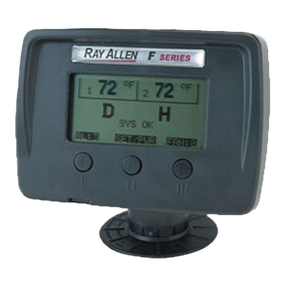
Deployment Heat Alert System Status System Status Back-light Level Fan Speed Button Label (Back-light) Button Label (Fan) Button Label (Press – Menus / Hold - Power) Drawing 2.1.2: HUD Display F3-G2 System Manual - Rev 7 Page 5 of 33... -
Page 6: Control Pod
Vehicle Interface Plug HUD Interface Jack On-Board Fuses Drawing 2.2.1: Control POD Top Reference Function Value (A) Window - Left Horn Lights Unlock Window - Right 20A Table 2.2.1: On-Board Fuse Values F3-G2 System Manual - Rev 7 Page 6 of 33... -
Page 7: Remote
Temperature Trend Arrows Sensor Temperatures Battery Level Signal Strength Heat Alert System Status Deployment System Status Button Label (Mute) Button Label (Press – Back-light / Hold - Power) Drawing 2.3.3: Remote/Pager Display F3-G2 System Manual - Rev 7 Page 7 of 33... -
Page 8: Starting The System
Once the option has been set to the desired value, pressing the center button will allow another option to be selected for editing. Holding the center button will exit out of the current sub-menu or menu. F3-G2 System Manual - Rev 7 Page 8 of 33... - Page 9 Drawing 4.1: System Menu Diagram F3-G2 System Manual - Rev 7 Page 9 of 33...
- Page 10 Drawing 4.2: System Menu Diagram - Advanced Settings F3-G2 System Manual - Rev 7 Page 10 of 33...
-
Page 11: System Message Descriptions
10 minutes NO SIGNAL XX:XX POD for the time specified after signal is lost (No beeper (approximate) if ‘MUTE’ is enabled) Table 5.2: Remote / Pager Message F3-G2 System Manual - Rev 7 Page 11 of 33... -
Page 12: Product Care And Service
LCD panel and the case. Do not submerge the RP in water. However, if the RP does become immersed in water, turn it off immediately. Allow the RP to completely dry before attempting to charge or turn it on again. F3-G2 System Manual - Rev 7 Page 12 of 33... -
Page 13: Troubleshooting
▪ Make note of the RF channel located in SETUP → ADVANCED → RF PARAMS. ▪ Turn on the RP, and while the Ray Allen logo is being displayed, quickly press and release the MUTE button. The RP will then allow you to adjust the serial number one digit at a time. -
Page 14: Installation
Doing so may “power down” this product and/or render it ineffective for its intended use. We recommend that you meet with the intended user to discuss preferences and installation requirements specific to the system’s application and user comfort. F3-G2 System Manual - Rev 7 Page 14 of 33... -
Page 15: Installation Kit Parts List
Kit Qty Reorder PN Antenna 10ft Antenna Cable Heads-Up Display (HUD) HUD Articulating Mount w/Hardware Pack (4 screws/nuts) Remote/Pager Unit Remote/Pager Holster 120V Remote Charger 1 In-Vehicle Remote Charging Pigtail F3-G2 System Manual - Rev 7 Page 15 of 33... - Page 16 Tip) Electrical Hardware None Pack POD & HUD None Attachment Hardware Pack (8 self-tapping screws) System Power Wire Harness (15ft) Vehicle Interface Wire Harness (15ft) Table 8.3.1: Parts List F3-G2 System Manual - Rev 7 Page 16 of 33...
-
Page 17: Charge The Remote
POD to the front panel of your K-9 insert or attach using 2-sided tape, Velcro® or any other attachment method you choose. Note: Take care to route all wires away from excessive heat sources and points of possible abrasion. F3-G2 System Manual - Rev 7 Page 17 of 33... -
Page 18: Electrical Specifications
Connect to black fan wire to blow into cage. (This output provides ground for the fan. Do NOT short to positive battery voltage.) Do NOT connect to more than one fan. See 8.17) MD10 F Ray Allen Fan Connection on page 26 for more information. Green... - Page 19 Window Lowering Feature Installation on page 21 for more information. Table 8.7.2: Vehicle Interface Wire Harness 14 13 12 11 10 Drawing 8.7.1: Connector Numbering Diagram (viewed from wire side) F3-G2 System Manual - Rev 7 Page 19 of 33...
- Page 20 Drawing 8.7.2: Typical Installation F3-G2 System Manual - Rev 7 Page 20 of 33...
-
Page 21: Window Lowering Feature Installation
Menu on page 8 for more information on adjusting this setting. blue / black blue purple / black purple Down wire cut here Window switch Window motor Up wire Drawing 8.8.1: Typical Window System Interface F3-G2 System Manual - Rev 7 Page 21 of 33... -
Page 22: Door Unlatch Solenoid Installation
Charger you locate the solenoid directly above the mid-door bracket and the window motor on a horizontal straight line with the door lock. The Ray Allen Cruise Eze™ door panels allow enough room for the installation of this solenoid in that location. -
Page 23: Door Unlock Feature Connection
The system's unlock pass-through wire is not used. unlock wire Vehicle unlock wire Lock motor Vehicle lock wire Drawing 8.10.2: Dual Switch Configuration F3-G2 System Manual - Rev 7 Page 23 of 33... -
Page 24: Stainless Steel Gas Push Rod Installation
Kennel insert more distance more force, less distance Door must be able to close completely before piston bottoms out. Drawing 8.11.2: Push Rod Mounting Considerations F3-G2 System Manual - Rev 7 Page 24 of 33... -
Page 25: Park / Neutral Safety Input
POD to a 3/4” hole drilled through the roof of the vehicle. The antenna connector is a modified NMO style terminal. The center contact and plastic washer must be removed in order to attach the antenna. Drawing 8.14.1: NMO Mount Modification F3-G2 System Manual - Rev 7 Page 25 of 33... -
Page 26: Temperature Sensor Placement
8.17 ) MD10 F Ray Allen Fan Connection The Ray Allen MD10 F Fan is designed to bolt directly to either side of the front panel on the Ray Allen Cruise Eze™. Hardware for this installation is included with the Fan. When attaching the Fan to the front panel of your Cruise Eze™, we suggest you insert the bolts... -
Page 27: Placement Of Heads Up Display (Hud)
Note: Take care to route the communication cable away from excessive heat sources or points of possible abrasion. On the facing of the dash On top of the dashboard Drawing 8.18.1: Example HUD Mounting Locations F3-G2 System Manual - Rev 7 Page 27 of 33... -
Page 28: Completing The Installation
Power up the system by pressing and holding down the center button on the front of the HUD. When the display appears, release the button. The HUD will run a self diagnostic routine. Upon completion of this routine proceed to the following steps. F3-G2 System Manual - Rev 7 Page 28 of 33... -
Page 29: Testing The Heat Alert™ System
(1) minute (the amount of time set as the ALERT DELAY). Note: When this test is completed successfully, we suggest that you reset the ALERT TEMP to 85F. F3-G2 System Manual - Rev 7 Page 29 of 33... -
Page 30: Testing The Tactical K9 Deployment System
On return to neutral or park, the “D” will become bold again. Note: After the test is completed successfully, we suggest that the WINDOW DROP option in the DEPLOYMENT Menu be set to “OFF”. F3-G2 System Manual - Rev 7 Page 30 of 33... -
Page 31: Confirming Normal Operation
Signal Strength is maximum......Drawing 8.22.2: Functional Battery Level is maximum....... Remote / Pager Display If the Remote/Pager will not connect to the system, see the troubleshooting section of the User's Manual. F3-G2 System Manual - Rev 7 Page 31 of 33... -
Page 32: Warranty
Series System is removed from the originally installed vehicle and installed into another vehicle. Warranty service requests are to be reported by phone to Ray Allen at (800) 444- 0404 or sent in writing via e-mail to Fseries@rayallen.com. Requests require the serial # of the System and original sales order number to be processed. -
Page 33: Disclaimer
10 ) Disclaimer Ray Allen Manufacturing, LLC can, at its discretion and without prejudice, make improvements to these products at any time. These improvements may or may not be made available to previously purchased products. This product is designed for sale and use within the United States of America and its territories.
Need help?
Do you have a question about the F3-G2 and is the answer not in the manual?
Questions and answers