
Summary of Contents for Detcon 700
- Page 1 Model 700 Remote Sensor/Alarm Relay Module Operator’s Installation and Instruction Manual...
- Page 2 700 RAM I.M. This page left intentionally blank 700 RAM I.M.
-
Page 3: Table Of Contents
Figure 4 Exploded View of Assembly ......................... 3 Figure 5 Interface connections on terminal board....................3 Figure 6 Installation with 700 Gas Sensor ......................4 Figure 7 Remote 700 Gas Sensor with RAM....................... 4 Figure 8 RAM Software Flowchart........................7... - Page 4 700 RAM I.M. This page left intentionally blank 700 RAM I.M.
-
Page 5: Introduction
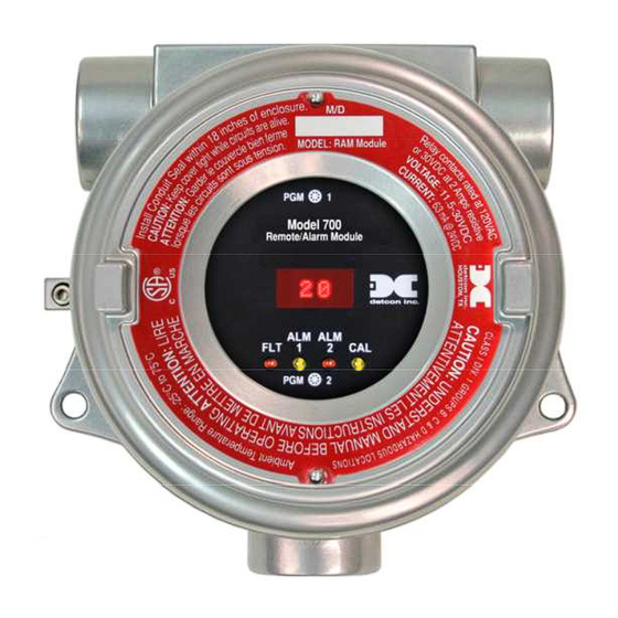
The Model 700 Remote Sensor/Alarm Relay Module (known as the Remote Alarm Module or RAM) is sold separately as an accessory for Model 700 Gas Sensors. It is a universal design and can be used with any of the Model 700 Gas Sensors. The RAM is provided in an explosion-proof junction box constructed of either epoxy-painted aluminum (Figure 1) or 316 stainless steel and includes a glass-viewing window. -
Page 6: Figure 2 Ram Mounting
Splash Guard 2" Figure 3 Mounting RAM with 700 Sensor The RAM Electronics package consists of three printed circuit assemblies (PCAs). The top two PCAs (RAM display and RAM connector board) and the RAM faceplate are enclosed in a molded plastic retaining guard and can be accessed by removing the junction box cover and using the brass pull knobs to pull the package directly out of the enclosure. -
Page 7: Field Wiring
The user will typically connect the 700 Gas Sensor directly to the RAM if there is no requirement for remote sensor separation (Figure 6). In this case, the 700 sensor will not require its own junction box and it is not 700 RAM I.M. -
Page 8: Figure 6 Installation With 700 Gas Sensor
RAM in the j-box, but only if it is ordered in this configuration. In this configuration, the wires from the 700 sensor will be directly connected to the 6-pin terminal block labeled “SENSOR” on the terminal board. -
Page 9: Operator Interface
The gas reading, gas units, and fault status reported by the RAM will mimic that of the 700 Gas Sensor. The Modbus™ output from the RAM repeats the Modbus™ output from the 700 Gas Sensor. - Page 10 Fault Settings Signal Output Check The user interface of the RAM is designed to mimic that of the Model 700 Gas Sensor. However, only the functions deemed critical for normal remote sensor operation are available. The 5 menu functions that are available for the remote control of the 700 Gas Sensor are: AutoZero –...
-
Page 11: Set-Up And Normal Operation
“ 0 ”. Once every 1 minute the LED display will flash the sensor’s measurement units and gas type (i.e. % LEL). If the 700 Gas Sensor or RAM is actively experiencing any diagnostic faults, a “Fault Detected” message will flash on the display once every minute. When the unit is in “Fault Detected” mode with the red Fault LED on, PGM1 or PGM2 can be swiped to invoke a display of the active faults. -
Page 12: View Sensor Status
Successful Modbus™ communications between the RAM and the RS-485 Master Controller will be indicated by a blinking “CAL” LED. If the Modbus™ communication between the RAM and the 700 Gas Sensor is not functioning the RAM will display “COMM” and the “FLT” LED will be illuminated. -
Page 13: Set Serial Id
The RAM can be polled serially via the RS-485 Modbus™ interface. It repeats the Modbus™ output from the 700 Gas Sensor it is connected to. The RAM Serial ID # should be set as a slave device to a master polling device. -
Page 14: Signal Output Check
700 RAM I.M. The menu item appears as: “Alarm1 Settings” From the “Alarm1 Settings” text scroll, hold the magnet over PGM1 () or PGM2 () until the arrow prompt appears and then hold continuously for an additional 3 seconds. The display will switch to “Set Level”... -
Page 15: Rs-485 Modbus Protocol
5. RAM Electronics Warranty Detcon Inc. warrants, under intended normal use, each new Model 700 RAM module to be free from defects in material and workmanship for a period of two years from the date of shipment to the original purchaser. -
Page 16: Specifications
Relay Contacts - Three Form C contacts rated for 5A @ 30 VDC/250 VAC RS-485 Modbus™ RTU Input Voltage 11-30VDC Power Consumption (excluding 700 Gas Sensor) < 0.5 Watts at 24VDC (Normal) < 1.0 Watts at 24VDC (Maximum) Operating Temperature -40°C to +75°C...
Need help?
Do you have a question about the 700 and is the answer not in the manual?
Questions and answers