
Summary of Contents for Axioma QALCOSONIC F2
- Page 1 Axioma LEZ UAB ULTRASONIC FLOW SENSOR QALCOSONIC F2 TECHNICAL DESCRIPTION, INSTALLATION AND USER INSTRUCTIONS PEF2V02 KAUNAS...
-
Page 2: Table Of Contents
Contents SAFETY INFORMATION ..........................3 APPLICATION FIELD ............................3 TECHNICAL DATA ............................. 5 OPERATING PRINCIPLE ........................... 7 MARKING AND SEALING ..........................7 SAFETY REQUIREMENTS ..........................7 INSTALLATION ..............................8 OPERATION ..............................10 VERIFICATION ..............................10 TRANSPORTATION AND STORAGE REQUIREMENTS................10 Annex A ................................. -
Page 3: Safety Information
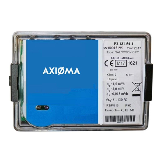
It is used in conjunction with the type approved heating/cooling energy calculator. As a component of heat energy meter the QALCOSONIC F2 flow sensor could be used for commercial account of energy quantity in district heating plants, in factories, in single or multifamily houses. - Page 4 Type number combination of the ultrasonic flow sensor: F2– 1 1 1 –NM - 1 - 0* QALCOSONIC Type Ratio of flow-rate limits (q Code =0,6 m (with the exeptions of sensors q /h; 1,0 m /h; 3,5 m Technical data of the flow sensor: Permanent Overall length, End connections...
-
Page 5: Technical Data
2. TECHNICAL DATA Accuracy class 2 by LST EN1434-1. Flow measurement The ratio of the permanent flow-rate to the lower limit of the flow-rate (the user selects during order): = 100, = 250 (with the exceptions of sensors q = 0,6 m or q /h;... - Page 6 Pulse outputs Class of flow output device OD according to EN1434-2 Pulse value is freely ordered of the range of values /imp (where N - possible number from 1 to 9, M - possible number from 1 to 6) Permissible minimal pulse value of volume and recommended pulse value, depending on the permanent flow rate: Table 1.2 Permanent flow rate q Permissible minimal pulse value...
-
Page 7: Operating Principle
3. OPERATING PRINCIPLE The flow measuring principle is based on ultrasonic measurement method. The ultrasonic signal along the measuring section moves many times upstream and downstream between the ultrasonic sensors, who alternately performs transmitter and receiver functions. From the resulting time difference the flow rate is calculated. Measured flow rate is converted into the pulses quantity that is transferred in output pulse terminal. -
Page 8: Installation
6. INSTALLATION 6.1. Basic requirements Before installing the device: - check if all parts listed in the documentation are available, - check if there are no visible mechanical defects, - check if there are valid labels of manufacturer and certification authority. Only qualified personnel may install the equipment, following the requirements listed in this document, in technical documentation of other system components and in heat meter installation project It is forbidden to wire signal cables nearby (less than 5 cm) with power cables or cables of other devices. - Page 9 Mounting on standard DIN-rail: Important: It is forbidden to attach the electronic unit directly to a wall if there is a risk that on walls can be condensed humidity or temperature of a surface of a wall can fall lower than 5 °. In this case, it is recommended to attach the calculator so that between it and wall surfaces there were an air gap not less than 5 cm.
-
Page 10: Operation
7. OPERATION Destination of contacts of connector J The 2-line, 10-pole connector is on the electronic unit plate. Destination of contacts of connector J is presented in fig. 7.1. Fig. 7.1. Destination of contacts of connector J Values of output pulses in test mode are presented in Table 7.1 Table 7.1. -
Page 11: Annex A
Annex A Electrical wiring diagrams of flow sensor QALCOSONIC F2 Fig.A1. Electrical wiring diagram PEF2V02 2017-11-20... - Page 12 Annex A Fig.A2. Wiring diagrams for connecting of the sensor to the external power supply Table A1. Numbering of terminals Terminal No. Destination Output pulses of volume (+) GND (-) Numbering of external power supply module terminals Terminal No. Destination 24 V AC/DC external power supply voltage 24 V AC/DC external power supply voltage PEF2V02...
-
Page 13: Annex B
Annex B Fig. B1. Mechanical dimensions of electronic unit of the flow sensor Fig.B2. Sizes and dimensions of the flow sensor Fig.B2.2. Threaded end connections G1“, Fig.B2.1. Threaded end connections G3/4“, Mounting length L=110 mm or L=165 mm mounting length L=130 mm Fig.B2.3. - Page 14 Annex B a) Threaded end connections G1 1/4 b) Flanged end connection DN25 PEF2V02 2017-11-20...
- Page 15 Annex B c) Flanged end connection DN32 Fig.B2.4. Threaded end connections G1 1/4“(a); Flanged end connection DN25 (b); Flanged end connection DN32 (c); mounting length L=260 mm PEF2V02 2017-11-20...
- Page 16 Fig.B2.5. Threaded end connections G2“(a); flanged end connection DN40 (b;c) (two design options) Mounting length L=300 mm PEF2V02 2017-11-20...
- Page 17 Annex B a) Dimensions of flow sensors DN50, DN65, DN80, DN100 ( Brass housing) DN65/PN16 DN65/PN25 DN80 DN100 b) Dimensions of flow sensors DN65, DN80, DN100 (Steel housing) Fig. B2.6. Dimensions of flow sensors DN50, DN65, DN80, and DN100 PEF2V02 2017-11-20...
-
Page 18: Annex C
Annex C Security sealing Fig.C1. Sealing of the electronic unit for flow sensor QALCOSONIC F2 Electronic general view: the cover is closed, and the cover is opened (1-Manufacturer security seal- adhesive sticker, 2-manufacturer warranty seal- adhesive sticker, 3 –mounting seal) a) Flow sensor G 3/4“... -
Page 19: Warranty
Warranty period - 12 months from bringing into operation, but not more than 18 months from manufacturing date. Manufacturer’s address: UAB “Axioma LEZ ”, Kulautuvos g. 45a, Kaunas LT-47190, Lithuania tel. +370 37 360234; fax. +370 37 360358. PEF2V02 2017-11-20...
Need help?
Do you have a question about the QALCOSONIC F2 and is the answer not in the manual?
Questions and answers