Advertisement
Table of Contents
- 1 Table of Contents
- 2 Section 1.0 Installation
- 3 Section 2.0 Operation
- 4 Section 3.0 Maintenance
- 5 Section 4.0 Disassembly
- 6 Section 5.0 Inspection
- 7 Section 6.0 Repair and Replacement
- 8 Section 7.0 Reassembly
- 9 Section 8.0 Test
- 10 Section 9.0 Illustrated Parts Breakdown (IPB) and Supplemental Data
- Download this manual
Visit www.boighill.com to request a quote.
Operation and
Maintenance Manual
MODEL S-216-J-( ) Series
AIR-DRIVEN HYDRAULIC PUMP
ISSUED NOVEMBER 1994
Revised February 2005
Sprague Products
Division of Curtiss-Wright Flow Control Corporation
10195 Brecksville Road
Brecksville, OH 44141 USA
Telephone: 440-838-7690 • Fax: 440-838-7513
www.cwfc.com
Visit www.boighill.com to request a quote.
Advertisement
Table of Contents

Summary of Contents for Sprague S-216-J Series
- Page 1 Operation and Maintenance Manual MODEL S-216-J-( ) Series AIR-DRIVEN HYDRAULIC PUMP ISSUED NOVEMBER 1994 Revised February 2005 Sprague Products Division of Curtiss-Wright Flow Control Corporation 10195 Brecksville Road Brecksville, OH 44141 USA Telephone: 440-838-7690 • Fax: 440-838-7513 www.cwfc.com Visit www.boighill.com to request a quote.
-
Page 2: Table Of Contents
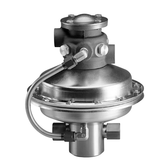
Visit www.boighill.com to request a quote. TABLE OF CONTENTS Page Section 1.0 Installation.................................4 Section 2.0 Operation................................4 Section 3.0 Maintenance ..............................5 Section 4.0 Disassembly ..............................5 Section 5.0 Inspection................................8 Section 6.0 Repair and Replacement............................8 Section 7.0 Reassembly ...............................9 Section 8.0 Test..................................11 Section 9.0 Illustrated Parts Breakdown (IPB) and Supplemental Data ................12 INTRODUCTION This Handbook provides the necessary information to install, operate service and overhaul the basic hydraulic pump, model S-216-J-( ). - Page 3 (Stainless Steel) S-216-J-( ) SERIES PUMP The Sprague Products pump develops high output pressure by applying the principle of differential ar- eas. The pump has a large area air piston, air-driven at low pressures. This air piston drives a small area fluid piston that in turn pumps liquids at high pressures.
-
Page 4: Section 1.0 Installation
Typical filter, regulator and lubricator assembly (FRL with air gauge installed. Do not exceed 100 p.s.i.g. inlet air pressure. Figure 1-2 Pump installed in typical circuit with recommended accessories which are available from Sprague Products. ®Teflon is a trademark of the DuPont Company. Visit www.boighill.com to request a quote. -
Page 5: Section 3.0 Maintenance
Visit www.boighill.com to request a quote. 2.2 STOP PUMP When the pump is disassembled, matched parts (i.e. fluid body and fluid piston) a. Close air shut-off valve. Normally should be kept together and handled care- after driving air supply has been fully to avoid damage to lapped or honed adjusted, the pump can be on-off surfaces. - Page 6 Visit www.boighill.com to request a quote. TROUBLE PROBABLE CAUSE CORRECTION (1a) PUMP IS NOT DELIVERING (a) Reservoir fluid supply is low. Add fluid as required. FLUID (pump running) (b) Fluid supply line to pump inlet check Remove and clean line. Check reservoir, its valve is clogged.
- Page 7 Visit www.boighill.com to request a quote. 4.11 Using o-ring removal tool, carefully remove the two Teflon retainers ® (18) and o-ring (17) from the seal groove in the fluid body (21). See Figure 4-13. Discard the old retain- ers and o-ring. 4.12 Using adjustable wrench, remove the inlet check valve assembly (22-25) from the fluid body port.
-
Page 8: Section 5.0 Inspection
0.004 0.102 gaskets, springs and detent pins at 150:1 -150 0.003 0.076 each pump overhaul. Overhaul kits from Sprague Products conveniently Figure 4-14 Removing check valves from fluid 200:1 -200 0.002 0.051 body. contain all necessary parts to prop- 300:1 -300 0.001... -
Page 9: Section 7.0 Reassembly
Visit www.boighill.com to request a quote. 7.2 Reassemble and install inlet and outlet check valves into fluid body (21). See Figure 7-1. Note order of assembly and position of poppets (23 and 33) by referring to Figure 7-2. Note torque instructions in illustrations. - Page 10 Visit www.boighill.com to request a quote. 7.8 Carefully insert assembled fluid in clockwise opposite positions: 12, 7.18 Install self-locking nut (44) on up- piston (16 or 27) and air piston (14) 6, 3, 9, etc. Uneven tightening will per threaded end of connecting rod assembly into bore of fluid body cause binding between cylinder (13) (37).
-
Page 11: Section 8.0 Test
Visit www.boighill.com to request a quote. 7.19 Check for smooth movement up Connecting Rod and down of shuttle. Using shop air (approx. 10 psi), inject air to elbow Self-Locking Nut in lower housing (19) to raise shuttle to up position. Manually push down At minimum, one on the shuttle. -
Page 12: Section 9.0 Illustrated Parts Breakdown (Ipb) And Supplemental Data
Visit www.boighill.com to request a quote. 8.0 IPB AND SUPPLMENTAL DATA 8239 Illustrated Parts Breakdown (IPB) enclosed to provide additional data on the S-216-J-() basic pump. Other pump data may be included as required. Exhaust air outlet port Driving air inlet port 45 46 49 Nameplate... - Page 13 Visit www.boighill.com to request a quote. Pump Ratio Dash Number Item Model Number Part Name -10 -20 -30 -35 -60 -100 -125 -150 -200 -300 S-216-J-10 Pump Assy., 10:1 Ratio (79293-11) • S-216-J-20 Pump Assy., 20:1 Ratio (77894-11) • S-216-J-30 Pump Assy., 30:1 Ratio (77894-21) •...
- Page 14 Visit www.boighill.com to request a quote. Pump Ratio Dash Number Item Model Number Part Name -10 -20 -30 -35 -60 -100 -125 -150 -200 -300 S-216-10-35 Liquid piston 79550-17-1* O-ring, 90 shore, nitrile MS28782-17 Packing retainer, Teflon 90098-35 Back-up ring —...
- Page 15 Visit www.boighill.com to request a quote. Pump Ratio Dash Number Item Model Number Part Name -10 -20 -30 -35 -60 -100 -125 -150 -200 -300 — 89803-300-1 Piston, body and housing assembly (See Note 4) 89793 Lower housing S-216-20 Gasket —...
- Page 16 Visit www.boighill.com to request a quote. Sprague Products Division of Curtiss-Wright Flow Control Corporation 10195 Brecksville Road Brecksville, OH 44141 USA Telephone: 440-838-7690 • Fax: 440-838-7513 www.cwfc.com © Sprague Products 2005 S216JOM 3M 205 Visit www.boighill.com to request a quote.
Need help?
Do you have a question about the S-216-J Series and is the answer not in the manual?
Questions and answers