
Related Manuals for ALDEN AE–1800

Summary of Contents for ALDEN AE–1800
- Page 1 AE–1800 Instruction Manual UM–AE1800–1.0 First Edition January, 2008 ALDEN NAVTEX RECEIVER MODEL AE – 1800 INSTRUCTION MANUAL...
- Page 2 AE–1800 Instruction Manual WARRANTY WARRANT MORCOM International, Inc. ( MORCOM ) warrants the AE–1800 NAVTEX Receiver and its active antenna ANT–2000 against defects in materials and workmanship for a period of one year from the date of shipping from the factory, during which time MORCOM will, at its option, either repair or replace the products that prove to be defective.
- Page 3 The information provided is not to be considered as a contractual specification. 3. USER’S RESPONSIBILITY The Alden Model AE–1800 NAVTEX Receiver obtains data transmitted from Government facilities. MORCOM International Inc. (MORCOM) makes no claim as to the accuracy, completeness or currency of the data since the AE–1800 only provides a means of receiving the data.
- Page 4 AE–1800 Instruction Manual WARNINGS < WARNINGS > 1. INSTALLATION & OPERATING ENVIRONMENT THE DISPLAY CABINET IS IN THE “PROTECTED” EQUIPMENT CATEGORY AS DEFINED UNDER IEC 60945(2002), AND IS NOT WEATHERIZED FOR OUTDOOR INSTALLATION/OPERATION. ANY DAMAGE CAUSED DIRECTLY OR INDIRECTLY THROUGH WATER INTRUSION IS NOT COVERED BY THE MANUFACTURER’S OR DEALER’S WARRANTY.
- Page 5 AE–1800 Instruction Manual CAUTIONS < CAUTIONS > 1: Operational – Memory Retention Period Do not leave the equipment switched off for more than 10 days continuously, or all stored messages will be erased, whether they are protected or not. Important messages you wish to preserve should be out put to an optional printer or to a PC via an appropriate rear panel interface connector if the unit is to be kept turned off for extended periods of time.
-
Page 6: Table Of Contents
AE–1800 Instruction Manual Index Typical NAVTEX Message Screen............. 1-1 1.1. Introduction......................1-1 1.2. Indication of Reception and Storage of New NAVTEX Message......1-6 Control Panel Functions ................. 2-1 Basic Operating Procedure............... 3-1 3.1. Introduction......................3-1 3.2. Turning the Equipment On /Off.................3-1 3.3. Adjusting Screen Brightness ................3-2 3.4. - Page 7 AE–1800 Instruction Manual Index 4.11.1. Introduction ....................4-12 4.11.2. Outpu t t ing Live NAVTEX Messages ..........4-13 4.11.3. Outputting All Stored Messages ............4-14 4.11.4. Outputting NAVTEX Messages of Specific Receiver ....4-15 4.11.5. Outpu t ting NAVTEX Messages of Specific Station ......4-16 4.11.6.
- Page 8 AE–1800 Instruction Manual Index 6.4. Self–Diagnostic Tests ..................6-2 6.5. Recommended Spare Parts................6-3 Installatio n .................... 7-1 7.1. Receiver Cabinet Installation................7-1 7.1.1. General Precautions ................7-1 7.1.2. Mounting the Receiver Cabinet..............7-1 7.2. Antenna Installation..................7-3 7.2.1. Installation Site Requirements ..............7-3 7.2.2. Precautions for Cabling ................7-3 7.3.
-
Page 9: Typical Navtex Message Screen
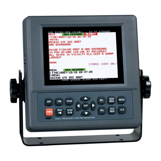
AE–1800 Instruction Manual Typical NAVTEX Message Screen Typical NAVTEX Message Screen 1.1. Introduction The illustration below represents a typical NAVTEX message screen, showing a new message received on the first ( 518 kHz) receiver. A similar screen will show up when the equipment is switched to receive a second receiver (490 kHz or 4209.5 kHz) message. - Page 10 AE–1800 Instruction Manual Typical NAVTEX Message Screen Typical NAVTEX Message Scree n ( continued – 2 / 6 1.1. Int roduction ( continued – 2 / 5 ③ Message Scrolling Keys The keys that can be used to manually scroll messages across the current screen are indicated.
-
Page 11: Introduction
AE–1800 Instruction Manual Typical NAVTEX Message Screen Typical NAVTEX Message Screen ( continued – 3 / 6 1.1. Introduction ( continued – 3 / 5 Message Identification ( Message ID) ⑥ The ID of the currently displayed message is shown here. A red–colored ID represents a warning message. - Page 12 AE–1800 Instruction Manual Typical NAVTEX Message Screen Typical NAVTEX Message Screen ( continued – 4 / 6 1.1. I n t r o d u c t i o n ( continued – 4 / 5 ⑧ New Message Tag IINEW MESSAGEII This indication ( tag) shows that the currently displayed NAVTEX text is a new...
- Page 13 AE–1800 Instruction Manual Typical NAVTEX Message Screen Typical NAVTEX Message Screen ( continued – 5 / 6 1.1. Introduction ( continued – 5 / 5 ⑪ Indication of Message Storage Status This indication shows whether or not the displayed NAVTEX message has been stored in the internal non–volatile memory.
-
Page 14: Indication Of Reception And Storage Of New Navtex Message
AE–1800 Instruction Manual Typical NAVTEX Message Screen Typical NAVTEX Message Screen ( continued – 5 / 5 1.2. Indication of Reception and Storage of New NAVTEX Message Indicating Reception of New Message – First Receiver ● The equipment visually indicates the reception of a new NAVTEX message by attaching a tag ) to the message ID, as in the example below. -
Page 15: Control Panel Functions
AE–1800 Instruction Manual Control Panel Functions Control Panel Functions The figure below shows the control panel of the equipment. A summary description of the functions the keys provides is given below and in the following pages. Figure 2-1 Control Panel ①... - Page 16 AE–1800 Instruction Manual Control Panel Functions Cont rol Panel Functions ( continued – 2 / 1 2 ② Power Key – 2 / 2 After the unit is switched on, the opening message window will be replaced with another window listing the current settings of receiver control parameters, as in the example below.
- Page 17 AE–1800 Instruction Manual Control Panel Functions Control Panel Functions ( continued – 3 / 1 2 ⑤ Screen Page Key Pressing this key switches the message screen between the first receiver screen page and the second receiver screen page. For example, if the current screen is currently showing the first receiver page ( i.e.
- Page 18 AE–1800 Instruction Manual Control Panel Functions Cont rol Panel Functions ( continued – 4 / 1 2 ⑧ Left Key ・ When a NAVTEX message is being displayed, a single press of this key scrolls the message text by one message forward timewise, displaying a newer message. ・...
- Page 19 AE–1800 Instruction Manual Control Panel Functions Control Panel Functions ( continued – 5 / 1 2 ⑪ Message/Station Selection Key – 1 / 2 ・ When the screen is showing a NAVTEX message, pressing this key displays a summary list of the transmitter IDs and message types that are currently selected as in the example below so that the equipment displays and stores messages of the selected types from the selected transmitters.
- Page 20 AE–1800 Instruction Manual Control Panel Functions 2. Cont rol Panel Funct i ons ( continued – 6 / 1 2 ⑪ Selection/Station Key – 2 / 2 ・ When option “ 4:MAKE SEL / REJ SETTING ” on the SYSTEM MENU is currently accessed for selection/rejection settings, this key selects the station or message type you specify for display and storage, and/or output to the I/O ports (RS–232C, RS–422 and I/O DATA connectors).
- Page 21 AE–1800 Instruction Manual Control Panel Functions Cont rol Panel Functions ( continued – 7 / 1 2 ⑫ Right Key ・ When a NAVTEX message is being displayed, a single press of this key scrolls the message text by one message backward timewise, displaying an older message. NOTE below.
- Page 22 AE–1800 Instruction Manual Control Panel Functions Cont rol Panel Fu n c t i o ns ( continued – 8 / 1 2 ⑬ New Message Key – 2 / 2 ・ The new message tag will be automatically removed 24 hours after reception of that message, even if you forget to acknowledge it.
- Page 23 AE–1800 Instruction Manual Control Panel Functions Cont rol Panel Functions ( continued – 9 / 1 2 ⑭ Message/Station Rejection Key – 1 / 2 ・ When a NAVTEX message text is currently being displayed, pressing this key turns on a summary list of the transmitter IDs and message types that are rejected ( deselected) via the menu system on both the first and second receivers as in the example below, and not to be displayed and stored.
- Page 24 AE–1800 Instruction Manual Control Panel Functions Control Panel Functions ( continued – 1 0 / 1 2 ⑭ Message/Station Rejection Key – 2 / 2 ・ When option “ 4:MAKE SEL / REJ SETTING ” on the SYSTEM MENU is currently accessed for selection/rejection settings, this key rejects the user–specified station or message type so that its messages are not to be displayed and stored in memory, not to be output to the printer port (RS–232C) or not to be output to the...
- Page 25 AE–1800 Instruction Manual Control Panel Functions Control Panel Functions ( continued – 11 / 1 2 ⑮ Menu Key ・ Pressing this key opens a menu termed “SYSTEM MENU,” as shown below, to customize the operation to suit your specific needs, to test the receiver performance off–line, or to reset the entire system to the initial settings.
- Page 26 AE–1800 Instruction Manual Control Panel Functions 2. Control Panel Functions ( continued – 1 2 / 1 2 ⑯ Store Message Key ・ This key is used to place a specific NAVTEX message in permanent storage, thereby protecting it from being automatically erased from memory after the maximum message storage limit ( 200 messages for each receiver) is reached.
-
Page 27: Basic Operating Procedure
AE–1800 Instruction Manual Basic Operating Procedure Basic Operating Procedure 3.1. Introduction This section describes the basic operating procedure, allowing you to operate your NAVTEX receiver from the front keypad without prior knowledge of the NAVTEX system. The functions that are available from the keypad are summarized in section 2 (Control Panel Functions). -
Page 28: Adjusting Screen Brightness
AE–1800 Instruction Manual Basic Operating Procedure Basic Operating Procedure – 2 / 7 3.3. Adjusting Screen Brightness ・ The screen brightness level can be changed in a total of eight steps to suit the ambient lighting condition by repeatedly pressing ・... -
Page 29: Scrolling Navtex Messages
AE–1800 Instruction Manual Basic Operating Procedure Basic Operating Procedure – 3 / 7 3.6. Scrolling NAVTEX Messages The displayed NAVTEX text can be scrolled line by line or down or message by message with the use of the following pairs of keys: ... -
Page 30: Stopping Audible And Visual Alarm
AE–1800 Instruction Manual Basic Operating Procedure Basic Operating Procedure – 4 / 7 3.7. Stopping Audible and Visual Alarm Your equipment will warn you audibly and visually upon reception of a vital NAVTEX message ( type–D message ), such as SAR information, piracy, or armed robbery warning. An example type–D alarm message is given below, showing the visual alarm ( called the alarm tag) attached to the message ID. -
Page 31: Protecting Messages For Permanent Storage
AE–1800 Instruction Manual Basic Operating Procedure Basic Operating Procedure – 5 / 7 3.8. Protecting Messages for Permanent Storage 3.8.1. Int roduction Initially, all stored NAVTEX messages will be automatically erased one by one from memory on a first–in–first–out basis as the equipment continues receiving new messages after the message storage capacity limit ( 200 messages) is reached. -
Page 32: Removing Protection Tag
AE–1800 Instruction Manual Basic Operating Procedure Basic Operating Procedure – 7 / 7 3.8.3. Removing Protection Tag The protection tag on a specific message can be removed via the following steps: (1) Using and/or , display the message from which you wish to remove the tag. -
Page 33: Customizing Operation Via Menu System
AE–1800 Instruction Manual Customizing Operation via Menu System Customizing Operation via Menu System 4.1. Introduction The equipment should work normally with the initial factory settings. Some of the settings, such as keypress beep on/off, screen background color, rejection of certain transmitters or message types and alarm on/off, however, may be changed to suit your specific operating needs via the menu system without degrading the performance. -
Page 34: Selecting Screen Background Colors
AE–1800 Instruction Manual Customizing Operation via Menu System 4.3. Selecting Screen Background Colors Figure 4-3 Selecting Screen Background Colors Three different colors (white, S Y S T E M M E N U black and blue) are selectable 1: MAKE DISPLAY SETTINGS for the text screen background. -
Page 35: Turning On/Off Screen Sleep Mode
AE–1800 Instruction Manual Customizing Operation via Menu System 4.5. Turning on/off Screen Sleep Mode 4.5.1. Introduction Figure 4-5 Turning Screen Sleep Mode on The screen brightness initially remains at the level set by S Y S T E M M E N U ... -
Page 36: Setting Times To Reduced Brightness Levels
AE–1800 Instruction Manual Customizing Operation via Menu System 4.5.3. Setting Times to Reduced Brightness Levels Figure 4-6 Setting Times to Reduced Brightness Levels If you wish to set the times to 2:TURN ON/OFF SLEEP MODE the reduced brightness levels, follow the steps given below. 1: OFF 2:TURN ON/OFF SLEEP MODE (1) Select option “... -
Page 37: Turning On/Off Keypress Beep
AE–1800 Instruction Manual Customizing Operation via Menu System 4.7. Turning on/off Ke ypress Beep Figure 4-8 Turning on / off Keypress Beep S Y S T E M M E N U Pressing a front panel key causes the equipment to 1: MAKE DISPLAY SETTINGS beep, indicating... -
Page 38: Selecting And Rejecting Transmitters
AE–1800 Instruction Manual Customizing Operation via Menu System 4.8. Selecting and Rejecting Transmitters 4.8.1. Introduction Initially the equipment is set to display NAVTEX messages from all stations on the air within the coverage area, store those messages in memory and output them to the printer port (RS–232C ), I / O DATA port and INS port ( RS–422). -
Page 39: Setting Procedure
AE–1800 Instruction Manual Customizing Operation via Menu System 4.8.2. Setting Procedure – 2 / 3 (2) Highlight the desired option, and then press . The above example shows that you selected option “ 2: F IRST REC EIVER ” to make settings to the first receiver alone. -
Page 40: Selecting And Rejecting Message Types
AE–1800 Instruction Manual Customizing Operation via Menu System 4.8.2. Set ting Procedure – 3 / 3 (7) Likewise, repeat steps (4), (5) and (6) to make the desired RJ/SL settings for other transmitter IDs. Do not press after setting the status with ... - Page 41 AE–1800 Instruction Manual Customizing Operation via Menu System 4.9.2. Set ting Procedure – 2 / 3 (2) Highlight the desired option, and then press . The example below shows that you selected option “ 1: SYNCHRONIZE BOTH RECEIVERS ” to make the same settings for the first and second receivers simultaneously.
- Page 42 AE–1800 Instruction Manual Customizing Operation via Menu System 4.9.2. Set ting Procedure – 3 / 3 Figure 4-14 Checking Statuses of Other Message Types – Example E : M E T E O R O L O G I C A L F O R E C A S T F: P I L O T S E RV I C E M E S S A G E G: A I S H: L O R A N –...
-
Page 43: Searching Memory For Stored Messages
AE–1800 Instruction Manual Customizing Operation via Menu System 4.10. Searching Memor y f or Stored Messages NAVTEX messages stored in non–volatile memory are searchable by station and / or message type via the following steps. (1) Highlight option “ 5: SEARCH FOR STORED MESSAGES ” by pressing ... -
Page 44: Selecting Output Messages
AE–1800 Instruction Manual Customizing Operation via Menu System 4.11. Selecting Output Messages 4.11.1. Introduction The NAVTEX message that is currently being received or previously received messages stored in memory can be output to external devices ( e.g., a printer, an INS/IBS device) via the rear panel interface connectors ( I / O p o r t s , i . -
Page 45: Outpu T T Ing Live Navtex Messages
AE–1800 Instruction Manual Customizing Operation via Menu System 4.11.2. Outpu t t ing Live NAVTEX Messages This output mode is to be activated when an optional printer is plugged in for realtime, on–line message printing or when a live NAVTEX output is required for other onboard applications. -
Page 46: Outputting All Stored Messages
AE–1800 Instruction Manual Customizing Operation via Menu System 4.11.3. Outputting All Stored Messages To output all the messages stored in memory, follow the steps given below. NOTE: A forced carriage return ( ) will be replaced by an underscore ( _ ) (hex 5F ) when it is output to an IBS / INS terminal or a printer. -
Page 47: Outputting Navtex Messages Of Specific Receiver
AE–1800 Instruction Manual Customizing Operation via Menu System 4.11.4. Outputting NAVTEX Messages of Specific Receiver If you wish to output all NAVTEX messages received from either receiver ( first or second receiver) alone, carry out the following step–by–step procedure: NOTE: A forced carriage return ( ) will be replaced by an underscore ( _ ) (hex 5F ) when it is output to an IBS / INS terminal or a printer. -
Page 48: Outpu T Ting Navtex Messages Of Specific Station
AE–1800 Instruction Manual Customizing Operation via Menu System 4.11.5. Outpu t ting NAVTEX Messages of Specific Station If you wish to output all messages received from a specific NAVTEX transmitting station, carry out the following step–by–step procedure: NOTE: A forced carriage return ( ) will be replaced by an underscore ( _ ) (hex 5F ) when it is output to an IBS / INS terminal or a printer. -
Page 49: Outputting Navtex Messages Of Specific Message Type
AE–1800 Instruction Manual Customizing Operation via Menu System 4.11.6. Outputting NAVTEX Messages of Specific Message Type If you wish to output all messages of a specific message type, carry out the following step–by–step instructions: NOTE: A forced carriage return ( ) will be replaced by an underscore ( _ ) (hex 5F ) when it is output to an IBS / INS terminal or a printer. -
Page 50: Outputting All Displayed Navtex Messages
AE–1800 Instruction Manual Customizing Operation via Menu System 4.11.7. Outputting All Displayed NAVTEX Messages If you wish to output all messages currently displayed, follow the steps given below. NOTE: A forced carriage return ( ) will be replaced by an underscore ( _ ) (hex 5F ) when it is output to an IBS / INS terminal or a printer. -
Page 51: Outputting Specific Navtex Message
AE–1800 Instruction Manual Customizing Operation via Menu System 4.11.8. Outputting Specific NAVTEX Message If you wish to output a specific message out of all currently displayed messages, carry out the following procedure: NOTE: A forced carriage return ( ) will be replaced by an underscore ( _ ) (hex 5F ) when it is output to an IBS / INS terminal or a printer. -
Page 52: Setting Output Ports
AE–1800 Instruction Manual Customizing Operation via Menu System 4.12. Setting Output Ports 4 . 1 2 . 1 . I n t r o d u c t i o n In order for external devices ( e.g. printer, IBS/INS component) to receive live or stored NAVTEX messages properly through the desired rear panel I/O connector ( RS–232C, RS–422 or I / O DATA connector), it is necessary to set the following parameters to the port selected. - Page 53 AE–1800 Instruction Manual Customizing Operation via Menu System 4.12.2.2. RS–422 Port The RS– 432 port, designed as an interface with an IBS/INS system, is also initially enabled so that the NAVTEX message types selected in paragraphs 4.11.2 through 4.11.8 will be output via this port. If, for any reason, you wish to disable it, follow the steps given below.
-
Page 54: Se Lecting Communications Protocols
AE–1800 Instruction Manual Customizing Operation via Menu System 4.12.3. Selecting Comm unications Protocols The following communications protocols are initially assigned to the three output ports described in paragraph 4.12. ・ IEC 61162–1 ( NMEA–0183 Ver. 2.0 & greater ): RS–422 Port ・... -
Page 55: Selecting Bit Formats And Data Transfer Rates
AE–1800 Instruction Manual Customizing Operation via Menu System 4.12.4. Selecting Bit Formats and Data Transfer Rates 4.12.4.1. Introduction The following instructions allow you to select the correct bit format ( number of data bits, stop bits, parity bit status) and bit rate ( baud rate: 110, 4800, 9600 etc.) that are required by the application using each I/O port for correct data transfer. - Page 56 AE–1800 Instruction Manual Customizing Operation via Menu System 4.12.4.2. Selecting Parameters for RS–232C Port ( continued – 2 / 2 If your RS–232C application requires a different set of parameters, select the appropriate values by following the steps given below: ...
- Page 57 AE–1800 Instruction Manual Customizing Operation via Menu System Selecting Parameters for I / O DATA Port 4.12.4.4. The parameters for the I/O DATA port are initially set as follows: ・ Data Bits: 8 bits ・ Stop Bits: 1 bit ・ Parity: Odd parity ・...
-
Page 58: Performing Sel F -Diagnostic Tests
AE–1800 Instruction Manual Customizing Operation via Menu System 4.13. Performing Sel f –Diagnostic Tests Figure 4-36 Starting Self–Diagnostic Test 4.13.1. Introduction S Y S T E M M E N U Selecting option “ 8: START 1: MAKE DISPLAY SETTINGS SELF–DIAGNOSTIC TESTS ”... -
Page 59: Checking Test Results
AE–1800 Instruction Manual Customizing Operation via Menu System 4.13.3. Checking Test Results Figure 4-37 Results of Self–Diagnostic Test – Example function will 8: START SELF–DIAGNOSTIC TESTS terminated automatically just SELF–DIAGNOSTIC TEST REPORT after completion of the keypad dimmer lamp test ( TESTING 1: TESTING RECEIVERS KEYPAD LAMPS on the test RCVR((518KHZ)((518KH... -
Page 60: Turning On/Off Message Alarms
AE–1800 Instruction Manual Customizing Operation via Menu System 4.14. Turning on/off Message Alarms The alarm function for types A ( navigational warning), B ( meteorological warning) and L ( additional navigational warning) messages is initially disabled unless it was already set otherwise by your dealer. -
Page 61: Reset Ting The System
AE–1800 Instruction Manual Customizing Operation via Menu System 4.15. Reset ting the S yste m If, for any reason, you wish to reset the system to return all current operational settings to the initial factory settings, follow the steps given below. Initialization of the settings does not affect the message storage;... -
Page 62: User-Level Troubleshooting
AE–1800 Instruction Manual User-Level Troubleshooting User–Level Troubleshooting A list of common troubles the user may experience while operating the equipment is given below along with recommended remedies for such troubles. If a problem persists, contact your dealer for assistance, giving as much information as possible about the symptom, self–diagnostic tests results ( paragraph 4.13 ), power supply voltage, antenna configuration, operating frequency, control and menu settings used, serial number of, software version (VER.) and revision (REV.) numbers of, your equipment. -
Page 63: No Message Reception
AE–1800 Instruction Manual User-Level Troubleshooting 5.2. No Message Reception The following description of the symptoms assumes that NAVTEX messages were properly received for some time after initial installation. Symptom Suggested Solution 1. Check the current message rejection (RJ) messages displayed ... - Page 64 AE–1800 Instruction Manual User-Level Troubleshooting No Message Reception – 2 / 3 5.2. Symptom Suggested Solution 1. Check if you are located within the service area covered by the ground wave of the desired station. The area is normally 200 to 400 nautical miles from each station No messages can be received in the during daytime hours.
-
Page 65: Message Storage Problems
AE–1800 Instruction Manual User-Level Troubleshooting No Message Reception – 3 / 3 5.2. Symptom Suggested Solution T he symptom is an indication that the antenna circuit has become defective. 1. Replace it with one known to be good. No messages can be received at any 2. -
Page 66: Poor Reception
AE–1800 Instruction Manual User-Level Troubleshooting 5.4. Poor Reception The following description of the symptoms assumes that NAVTEX messages were properly received for some time after initial installation time, and all message types and transmitter IDs you wish to receive are selected ( via the steps in paragraphs 4.8 & 4 .9 ). Symptom Suggested Solution 1. -
Page 67: Blank Message Screen
AE–1800 Instruction Manual User-Level Troubleshooting 5.5. Blank Message Screen The following description of the symptom assumes that your NAVTEX receiver was properly working for some time after initial installation time. Symptom Suggested Solution 1. Check to be sure that the power source voltage is within the 11–36V range. -
Page 68: No Response From Keypress
AE–1800 Instruction Manual User-Level Troubleshooting 5.8. No Response from Ke ypress The following description of the symptom assumes that your NAVTEX receiver was properly working for some time after initial installation time. Symptom Suggested Solution 1. Check to be sure that the power source voltage is within the 11–36V range. -
Page 69: No Message Alarm Output
AE–1800 Instruction Manual User-Level Troubleshooting 5.10. No Message Alarm Output The following description of the symptom assumes that your NAVTEX receiver was properly working for some time after initial installation time. Symptom Suggested Solution 1. The alarm function for type–A and type–B messages are initially disabled. -
Page 70: External Control Problem
AE–1800 Instruction Manual User-Level Troubleshooting 5.12. External Control Problem The following description of the symptom assumes that your NAVTEX receiver was properly working for some time after initial installation time. Symptom Suggested Solution 1. Check to be sure that the RS–422 ( INS) port enabled ( set... -
Page 71: User-Level Maintenance Instructions
AE–1800 Instruction Manual User-Level Maintenance User–Level Maintenance Instructions To ensure long–term trouble–free operation, the user should regularly follow the maintenance instructions described in this section. 6.1. Maintenance on the Equipment Cabinet Keep the equipment, away from sea splashes, direct sunlight and other heat–generating sources, and make sure that air around the cabinet is circulating freely. -
Page 72: Maintenance On The Active Antenna Unit
AE–1800 Instruction Manual User-Level Maintenance 6.3. Maintenance on The Active Antenna Unit The ANT–2000M active antenna or an optional active antenna unit ( e . g . ANT– 900 , a l l consisting of a 1.2m fiberglass whip, a preamplifier housing and coaxial cabling), requires maintenance at least once every six months: 1. -
Page 73: Recommended Spare Parts
AE–1800 Instruction Manual User-Level Maintenance 6.5. Recommended Spare Parts A list of the spare parts recommended for the maintenance and servicing for three to five years is given below. Replacing parts, except for the active antenna unit, should be done by your dealer or a qualified service engineer. The user should not open the receiver cabinet for inspection or replacing suspected parts. -
Page 74: Installation
AE–1800 Instruction Manual Installation Installation 7.1. Receiver Cabinet Installation 7.1.1. General Precautions The receiver cabinet is constructed to withstand the humid and corrosive marine environment, but is designed to be installed or operated inside the wheelhouse or chartroom. The cabinet is a “protected” category product under the IEC 60945–2002 standard, and is not waterproof. - Page 75 AE–1800 Instruction Manual Installation – 7.1.2. Mounting the Display Cabinet ( continued 2 / 2 Be sure to attach a serrated plastic washer to the inside of each arm before placing the cabinet in the bracket. This pair of washers is supplied separately in the plastic bag that contains the power cable, fuses, plugs, etc., and prevents the cabinet from leaning forward or backward with the clamping knobs tightened.
-
Page 76: Antenna Installation
AE–1800 Instruction Manual Installation 7.2. Antenna Installation The dimensions of the active antenna unit (ANT–2000M) is given in Figure 7–2.. The equipment does not support the use of a wire antenna. The receiver input is low impedance and is not suitable for wire antenna connection. 7.2.1. - Page 77 AE–1800 Instruction Manual Installation Precautions for Cabling ( continued –2 / 2 7.2.2. Figure 7-2 ANT–2000M Active Antenna Unit Dimensions The dimensions are in millimeters except for the socket section at the base of the preamplifier housing. The socket is internally threaded so that it can accept a 1”–14 straight thread standard marine pole.
-
Page 78: Electrical Connections
AE–1800 Instruction Manual Installation 7.3. Electrical Connections 7.3.1. Introduction All electrical connections to the equipment are to be made via the connector receptacles and terminal installed on the rear panel and the rear apron. The figure below shows the rear view of the equipment. Overall connections are illustrated in Figure 7–4. A summary description of the necessary connections to each component is given in the next paragraphs. - Page 79 AE–1800 Instruction Manual Installation 7.3.1. Int roduction ( continued –2 / 2 Figure 7-4 Overall Connections...
-
Page 80: Connector Pin Assignments And Connections
AE–1800 Instruction Manual Installation 7.3.2. Connector Pin Assignments and Connections The pin assignments of the connectors and connections to the pins are illustrated below. ① Power Supply Receptacle Figure 7-5 Power Supply Receptacle ( Front View) Pin # 3 (Ground ) Pin # 1 ( 24V+) Pin # 2 ( –... - Page 81 AE–1800 Instruction Manual Installation 7.3.2. Connector Pin Assignments and Connections ( – continued 2 / 8 ③ Fuse Holder Figure 7-7 Fuse Holder A 3–ampere (3A) cartridge fuse ( 5.2X20 mm, slow–blow type) is inserted in the holder. Reversing the power cable polarity causes the fuse to blow. <...
- Page 82 AE–1800 Instruction Manual Installation 7.3.2. Connector Pin Assignments and Connections ( – continued 3 / 8 ⑤ RS–422 Connector Connections from an IBS/INS device are to be plugged into this receptacle. A D–Sub 9 female type plug mates with this connector. The pin assignments are illustrated below.
- Page 83 AE–1800 Instruction Manual Installation 7.3.2. Connector Pin Assignments and Connections ( – continued 4 / 8 RS–422 Transceiver Data Sheet – 1 / 3...
- Page 84 AE–1800 Instruction Manual Installation 7.3.2. Connector Pin Assignments and Connections ( – continued 5 / 8 RS–422 Transceiver Data Sheet – 2 / 3...
- Page 85 AE–1800 Instruction Manual Installation 7.3.2. Connector Pin Assignments and Connections ( – continued 6 / 8 RS–422 Transceiver Data Sheet – 3 / 3...
- Page 86 AE–1800 Instruction Manual Installation 7.3.2. Connector Pin Assignments and Connections ( – continued 7 / 8 ⑥ RS–232C Connector An optional serial printer (PR–900) is to be plugged into this receptacle. A D–Sub 9 female type plug mates with this connector. The pin assignments are illustrated below.
- Page 87 AE–1800 Instruction Manual Installation 7.3.2. Connector Pin Assignments and Connections ( – continued 8 / 8 ⑦ I / O DATA Connector The I/O DATA port is primarily for data communications with other onboard devices using IEC 61162–1 ( NMEA–0183 ) as the interface. It also provides a port ( comprising pins #4, #5 and #6) for software updating, and a regulated 12V DC 200 mA output for powering light–duty applications.
-
Page 88: Ins Port Data And Command Sentences
AE–1800 Instruction Manual Installation 7.4. INS Port Data and Command Sentences The equipment supports the following IEC 61162–1 data sentence formats for communications with an INS / IBS system via the RS–422 port. It is assumed that the port is set to “ON” via the procedure given in paragraph 4.12.2.2. 7.4.1. - Page 89 AE–1800 Instruction Manual Installation 7.4.1. Received NAVTEX Sentence Format ( continued –2 / 2 An example 518 kHz NAVTEX message text is given below. IB45 260909 UTC MAR 07 WWJP83 RJTD 260600 VITAL WARNING FOR YOKOHAMA NAVTEX AREA 260600UTC ISSUED AT 260900UTC COLD FRONT FROM 48N 157E TO 42N 156E 36N 151E 30N 147E 25N 140E GALE WARNING WESTERN SEA OFF SANRIKU...
-
Page 90: Controlling Receiver Operation Via Ins (Rs-422) Port
AE–1800 Instruction Manual Installation 7.4.2. Controlling Receiver Operation via INS (RS–422) Port To externally control receiver operation via the RS–422 port, the equipment supports the following command sentence ( IEC 61162–1 format ). Up to 10 commands will be stacked and executed sequentially. Using the transmitter mask and message mask, the user can select the station IDs and message types for message storage in the non–volatile memory, for message output to the RS–422 port ( INS port ) or to the RS–232C port ( printer port ). -
Page 91: Checking Current Settings Via Ins (Rs-422) Por T
AE–1800 Instruction Manual Installation 7.4.3. Checking Current Settings via INS (RS–422) Por t The equipment accepts the following query command sentence via the RS–422 port (INS port), and reports to the user the current B mask settings, indicating the status of message storage in the non–volatile memory, and message output to the INS port and the RS–232C port ( printer port) for all frequencies. -
Page 92: Alarm Output Sentence Formats
AE–1800 Instruction Manual Installation 7.4.4. Alarm Output Sentence Formats 7.4.4.1. Output Format for Alarm Being Activated An alarm output sentence like the example below will be output to the RS–422 (INS) port when the equipment receives an alarm NAVTEX message or if the equipment develops a failure or malfunction. -
Page 93: Alarm Acknowledgement
AE–1800 Instruction Manual Installation 7.4.4.3. Output Format After Alarm Being Acknowledged Within one minute after the issuance of the above sentences or after the key is pressed twice, the following outputs will be repeated at one–minute intervals. This condition will continue until another alarm message is received. $CRALR 14 <... -
Page 94: Summarized Theor Y Of Operation
AE–1800 Instruction Manual l Theory of Operation Summarized Theor y of Operation 8.1. What is NAVTEX? NAVTEX, a system of broadcast and automatic reception of global maritime safety information by means of direct display/printing telegraphy, is part of the GMDSS infrastructure, defined by IMO Assembly resolution A.706 (17). -
Page 95: Navtex Receiver - General
AE–1800 Instruction Manual l Theory of Operation 8. Summarized Theor y of Operation ( – 2 /10 ) continued 8.5. NAVTEX Receiver – General A NAVTEX receiver that complies with the relevant IMO resolutions and regulations for wheel mark certification is programmed to automatically receive and display/print a message, and avoids a repeated reception of the same message by checking the ID and numbering of each message. - Page 96 AE–1800 Instruction Manual l Theory of Operation 8. Summarized Theory of Operation ( – continued 3 / 10 8.7. Operating Principle of AE–1800 Figure 8–1 shows interconnections between the printed circuit boards (PCBs) comprising the AE–1800 system and interface connections from the PCBs to data input/output ports and peripheral devices.
-
Page 97: Operating Principle Of Ae-1800
AE–1800 Instruction Manual l Theory of Operation 8. Summarized Theory of Operation ( – continued 4 / 10 8.7. Operat ing Principle of AE–1800 ( continued –2 / 2 CPU Circuit The Main PCB (M613–MAIN–X) carries a CPU circuit and a power supply circuit. The CPU is a 16–bit single–chip microcomputer (U10) clocked at 24 MHz by crystal–controlled oscillator X1, and on–chip flash ROM for program software and on–chip RAM providing memory space for data processing of the demodulated signals. - Page 98 AE–1800 Instruction Manual l Theory of Operation 8. Summarized Theory of Operation ( – continued 5 / 10 Figure 8-1 Interconnections continued on next page...
- Page 99 AE–1800 Instruction Manual l Theory of Operation 8. Summarized Theor y of Operation ( – continued 6 / 10 Figure 8-2 Functional Block Diagram – Receiver Board...
- Page 100 AE–1800 Instruction Manual l Theory of Operation 8. Summarized Theor y of Operation ( – continued 7 / 10 Figure 8-3 CPU Circuit – Main Board...
- Page 101 AE–1800 Instruction Manual l Theory of Operation 8. Summarized Theor y of Operation ( – continued 8 / 10 Figure 8-4 Power Supply Circuit – Main Board...
- Page 102 AE–1800 Instruction Manual l Theory of Operation 8. Summarized Theor y of Operation ( – continued 9 / 10 Figure 8-5 LCD Backlight Control Circuit – Main PCB...
- Page 103 AE–1800 Instruction Manual l Theory of Operation 8. Summarized Theor y of Operation ( – continued 10 / 10 Figure 8-6 Keypad Board...
- Page 104 AE–1800 Instruction Manual Specifications Specifications (1) IEC 60945–2002 Equipment Category: ・ Receiver Cabinet : Protected ・ Active Antenna Unit : Exposed (2) Receive Frequencies : ・ First Receiver : 518 kHz ・ Second Receiver : 490 kHz and 4209.5 kHz, front panel–selectable or by proprietary command sentence via RS–422 port (3) Type of Receiver : ・...
-
Page 105: Specifications
AE–1800 Instruction Manual Specifications Specifications ( – continued 2 / 4 ( 14 ) Text Display: ・ NAVTEX Messages : 40 characters per line, 18 lines per screen. A forced ( ) divides the last word at carriage return symbol 40th character position if the number of character in a line exceeds 40. - Page 106 AE–1800 Instruction Manual Specifications Specifications ( – continued 3 / 4 ( 19 ) Message ID Storage: ・ Capacity : 200 IDs of successfully received messages (with CER ≦33%) on each of 518 kHz, 490 kHz and 4209.5 kHz ・ Duration : 60 hours 20 minutes after receipt or until the storage limit ( 200 for each frequency) is reached .
- Page 107 AE–1800 Instruction Manual Specifications Specifications ( – continued 4 / 4 ( 25 ) Compass Safe Distances ( in Energized Condition ): ・ Cabinet with Bracket: 60 cm ( standard ), 35 cm ( steering ) ・ Cabinet only: 45 cm ( standard ), 30 cm ( steering ) ( 26 ) Ambient Temperatures: –...
-
Page 108: List Of Alarms
AE–1800 Instruction Manual l List of Alarms List of Alarms 10.1. Message Alarms Alarm for D–Type Message ● ・ Enabled / Disabled Status: Enabled at all times. ・ Triggering Condition: To be triggered upon reception of a D–type message. ・ User Interface: - Audible: Beeping at approx. -
Page 109: List Of Abbreviations
AE–1800 Instruction Manual List of Abbreviations 11. List of Abbreviations The abbreviations used in this manual and menus, on screen, control panel and rear panel are listed below. amperes ACKNLG: Acknowledge Automatic identification system ( typical device identifier of AIS equipment ) AIS: Automatic identification system ALM:... - Page 110 AE–1800 Instruction Manual List of Abbreviations – c o n t in u e d 2 / 2 List of Abbreviations ( meters milliamperes min: minutes millimeters ME or MEM : Memory ( non–volatile memory for message storage) MF : Medium frequency broadcast band ( including 490 kHz and 518 kHz ) MON : Monitor ( audible monitor )
-
Page 111: User Settings To Be Stored In Non-Volatile Memory
AE–1800 Instruction Manual User–made Settings 12. User Settings To Be Stored in Non–Volatile Memory The following user–made settings will be stored in the non–volatile memory. Settings indicated in Italic type fonts are factory defaults. Screen Brightness Level: Last used level ●... - Page 112 AE–1800 Instruction Manual User–made Settings 12. User Settings To Be Stored in Non–Volatile Memory ( continued –2 / 2 ・ Message Output ( for printing live messages on–line ) - RECEIVING MSG: ON, OFF Message Alarms On/Off ・ - Type A Message: ON, OFF - Type B Message: ON, OFF...
-
Page 113: List Of Components To Be Shipped
AE–1800 Instruction Manual List of Components To Be Shipped 13. List of Components To Be Shipped The following set of components is usually shipped by the manufacturer, either as standard or optionally. The same information is usually given in the shipping documents ( INVOICE, PACKING LIST, e t c . - Page 114 AE–1800 Instruction Manual MORCOM INTERNATIONAL, INC. 3656 Center view Drive, Unit #1 Chant ill y, VA 20151, U. S. A. 1st Edition, January., 2008 UM–AE1800–1.0 Printed in Japan...
Need help?
Do you have a question about the AE–1800 and is the answer not in the manual?
Questions and answers