
Related Manuals for Funkwerk TRT800H-OLED


Summary of Contents for Funkwerk TRT800H-OLED
- Page 1 TRT800H - OLED Mode S Transponder P/N 800ATC-H-(2xx)-(2xx) Operation and Installation (Document-No. 03.2124.010.71e)
- Page 2 TRT800H / P/N 800ATC-H-(2xx)-(2xx) Operation and Installation Change History Revision Date Description of Change 1.00 18.11.2011 First Release List of Service-Bulletins (SB) Service Bulletins have to be inserted into this manual and to be enlisted in the following table. Rev. Insertion SB No Issue Date...
-
Page 3: Table Of Contents
TRT800H / P/N 800ATC-H-(2xx)-(2xx) Operation and Installation Table of Contents GENERAL ..................5 Symbols ...................5 Abbreviations ................6 Customer Support ..............7 Features ...................8 OPERATION ..................9 Controls..................9 ON/OFF..................11 Display-Brightness ..............11 Display-Indications ..............11 Flight-ID (FID) ................13 2.5.1 Display Flight-ID ............13 2.5.2 Configure Flight-ID ............13 Transponder Mode selection..........14 Squawk-Setting ..............15 VFR –... - Page 4 TRT800H / P/N 800ATC-H-(2xx)-(2xx) Operation and Installation 3.8.1 Antenna Selection ............24 3.8.2 Installation Recommendation ........24 3.8.3 Antenna Wiring ............25 Post-Installation Check ............25 3.10 Starting Up ................26 3.11 Accessories................26 3.12 Drawings ................27 3.12.1 Dimensions..............27 3.12.2 Mounting Advices ............27 SETTINGS ..................28 Overview ................28 4.1.1 Error Logging...............28 4.1.2 ICAO 24-Bit Aircraft Address (AA).......28 4.1.3 Aircraft Category (AC) ..........29...
-
Page 5: General
TRT800H / P/N 800ATC-H-(2xx)-(2xx) Operation and Installation GENERAL This manual contains information about the physical, mechanical and electrical characteristics and about installation and operation of the Mode S Transponder TRT800H. Symbols Advices whose non-observance can cause radiation damage to the human body or ignition of combustible materials Advices whose non-observance can cause damage to the device or other parts of the equipment. -
Page 6: Abbreviations
TRT800H / P/N 800ATC-H-(2xx)-(2xx) Operation and Installation Abbreviations Abb. Meaning Explanation Flight ID Flight plan number or if not assigned registration number of aircraft Special Position Activation on request by controllers Identification „Squawk Ident“, transmits SPI Pulse for 18 seconds, which highlights the respective traffic item on the controllers radar screen Aircraft Address... -
Page 7: Customer Support
„Reshipment RMA“ provided at the Service-Area within the Funkwerk Avionics web portal www.funkwerk- avionics.com. Any suggestions for improvement of our manuals are welcome. Contact: service@funkwerk-avionics.com. Informations on software updates are available at Funkwerk Avionics Document-No: 03.2124.010.71e / Revision: 1.00... -
Page 8: Features
TRT800H / P/N 800ATC-H-(2xx)-(2xx) Operation and Installation Features In order to operate the Mode-S transponder it is necessary to request an ICAO 24-Bit Aircraft Address at the responsible national aviation authorities. The received Code is assigned to the specific transponder/aircraft and must be configured within the transponder. -
Page 9: Operation
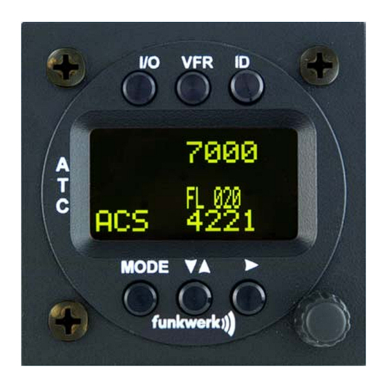
TRT800H / P/N 800ATC-H-(2xx)-(2xx) Operation and Installation OPERATION Controls Activate/ deactivate VFR „Squawk Ident“ ON / OFF Active Squawk Operation Mode Standby (Mode) Squawk Cursor adjustment Select Operation Mode Rotary Knob Change for adjusting values Active Standby at the cursor position Squawk Document-No: 03.2124.010.71e / Revision: 1.00... - Page 10 TRT800H / P/N 800ATC-H-(2xx)-(2xx) Operation and Installation Switch ON press button for approx. 0,5 s ON/OFF Switch OFF press button for approx. 3 s 1. activate/deactivate VFR Squawk (press shortly) 2. store active Squawk as VFR/VFRW- Squawk (press button 3 s) see section. 2.8 1.
-
Page 11: On/Off
TRT800H / P/N 800ATC-H-(2xx)-(2xx) Operation and Installation ON/OFF press button for Switch ON: 0.5 s press button for Switch OFF: After turning-on the display appears as follows: Device Name Software-Version Firmware-Version (Example) If more than one aircraft address/FID exists, select the correct entry with the rotary knob and confirm with . - Page 12 TRT800H / P/N 800ATC-H-(2xx)-(2xx) Operation and Installation Value Meaning Remarks Transponder is transmitting: Replies on Interrogations Appears per reply Extended Squitter (ADS-B out) diamond 7000 active Squawk Transponder is locked by a Lock Information (indicated ground station and will be as vertical dash below the directly addressed diamond)
-
Page 13: Flight-Id (Fid)
TRT800H / P/N 800ATC-H-(2xx)-(2xx) Operation and Installation Flight-ID (FID) The FID is an identifier required by Mode-S Operation. During future application of flight plans a FID could be assigned on a per flight basis. If no FID is assigned (today’s normal case) the registration marking of the aircraft should be used as FID. -
Page 14: Transponder Mode Selection
TRT800H / P/N 800ATC-H-(2xx)-(2xx) Operation and Installation Please refer to section 4.2.1 for configuration of the 24-bit Address (AA) and Aircraft Category (AC). Transponder Mode selection Press (repeatedly) to select from following Modes: • STBY „Standby“ Transponder does not respond to any interrogation. Squitter and ADS-B output is not active. -
Page 15: Squawk-Setting
TRT800H / P/N 800ATC-H-(2xx)-(2xx) Operation and Installation Squawk-Setting The active Squawk is displayed in the upper line, while the standby Squawk is presented at the lower line. Setting the Standby Squawk: • Press to set the cursor („^“), turn rotary knob to set numbers of the standby Squawk. -
Page 16: Id - Special Position Identification (Spi): "Squawk Ident
TRT800H / P/N 800ATC-H-(2xx)-(2xx) Operation and Installation ID – Special Position Identification (SPI): “Squawk Ident” Press ID to activate transmission of the special position identification pulse with every reply within 18 seconds; “IDT” appears on the display By pressing a special position identification pulse (SPI) is transmitted with every reply within 18 seconds, which causes an accented marking on the Controller’s screen. -
Page 17: Installation
Techniques and Practices – Aircraft Alterations“ and the appropriate manufacturer’s instructions. Telecommunication data Depending on your national telecommunications legislation, the following data may be required when applying for the aircraft radio station license: Manufacturer: Funkwerk Avionics GmbH Type Designation: TRT800H EASA Number: EASA.21O.269 Transmitter Power Output... -
Page 18: Unpacking And Inspecting Of The Equipment
• In cooperation with a maintenance shop, location and kind of the installation are specified. The maintenance shop can supply all cables. Suitable sets of cables are available from Funkwerk Avionics GmbH. • Select a position away from heat sources. Care for adequate convection cooling. -
Page 19: Equipment Connections
TRT800H / P/N 800ATC-H-(2xx)-(2xx) Operation and Installation Equipment Connections 3.6.1 Electrical Connections One 15 pin D-SUB miniature connector includes all electrical connections, except for the antenna. Use only an External Memory Adapter TRT800EM or TRT800EMSS as they are part of the certification and include a memory with the stored ICAO 24bit Aircraft Address. -
Page 20: Static Air Port
TRT800H / P/N 800ATC-H-(2xx)-(2xx) Operation and Installation 3.6.1.3 Auto-On The Auto-On input allows to define how the transponder will behave when power is supplied to it. If the aircraft is equipped with a dedicated avionics master switch that switches the power supply to the transponder, the pin "Auto-On" must be wired together with the UB+ pin to the avionic master switch. -
Page 21: Wiring
TRT800H / P/N 800ATC-H-(2xx)-(2xx) Operation and Installation Wiring 3.7.1 Conductor Cross Section Power Supply (Power, GND): AWG20 (0,62 mm²) Signals: AWG22 (0,38 mm²) The conductors must be approved for aircraft use. 3.7.2 Pin Assignment The transponder may only be operated together with an external memory address adaptor (TRT800EM/TRT800EMSS)! Pin Signal... -
Page 22: Trt800Em - External Memory
TRT800H / P/N 800ATC-H-(2xx)-(2xx) Operation and Installation SWITCHED +UB May only be used for compatible Funkwerk Avionics devices. Auto-On Connect to +UB override front panel on/off button. Leave unconnected tu use front panel on/off button. Ground Switch/ If an external Ground Switch is connected, it must... -
Page 23: Trt800Emss - External Memory (With Rs232)
TRT800H / P/N 800ATC-H-(2xx)-(2xx) Operation and Installation 3.7.4 TRT800EMSS – External Memory (with RS232) DSUB 15pol DSUB 9pol white < PIN-5 > <PIN-2 black < PIN-12> <PIN-3 yellow FLY_GND < PIN-15> <PIN-7 SUPP_I/O < PIN-13> <PIN-8 <PIN-5 Shielded cable GND <PIN-9 <... -
Page 24: Antenna
TRT800H / P/N 800ATC-H-(2xx)-(2xx) Operation and Installation Antenna 3.8.1 Antenna Selection • Recommended antennas: see section 3.11 Accessories • Choose an antenna type compatible with the vehicle and the mounting location. • Specified features depend on proper installation of the antenna. •... -
Page 25: Antenna Wiring
TRT800H / P/N 800ATC-H-(2xx)-(2xx) Operation and Installation 3.8.3 Antenna Wiring • Suitable antenna cables: see section 3.11 Accessories • Keep wiring as short as possible. • The smallest cable bend radius is 10cm. Avoid sharp bends. • Keep away from an ADF antenna cable at least 12 inches. •... -
Page 26: Starting Up
TRT800H / P/N 800ATC-H-(2xx)-(2xx) Operation and Installation 3.10 Starting Up Turn the transponder on with After start-up the following screens appear: The TRT800H starts in Standby Mode (indicated with STBY). In order to change into operational mode (indicated with ACS) press Very important is the correct configuration of the 24bit Aircraft-Address (see 4.2.1 Setup Steps). -
Page 27: Drawings
TRT800H / P/N 800ATC-H-(2xx)-(2xx) Operation and Installation 3.12 Drawings 3.12.1 Dimensions Power/RS232 TRT800 Static Air TRT800H Antenna 65 mm Ø 57 mm 170 mm 15 mm 20mm 3.12.2 Mounting Advices Connections Area Panel Cut-out Ø 57,5 mm 4 x Ø 4 mm 47,0 mm Fixing clips (spring) left / right... -
Page 28: Settings
TRT800H / P/N 800ATC-H-(2xx)-(2xx) Operation and Installation SETTINGS Overview The TRT800H is capable of storing the following information: • ICAO 24-Bit Aircraft-Address (AA), see section 4.2.1 • Aircraft Category (AC), see section 4.1.3, e.g. o „19“ for gliders o „21“ for aircrafts with a MTOW below 15.500 lbs, motor glider o „1C“... -
Page 29: Aircraft Category (Ac)
TRT800H / P/N 800ATC-H-(2xx)-(2xx) Operation and Installation Only the assigned AA has to be used and must not be modified at any time, because a duplicate address would jeopardize the data surveillance and integrity figures of Mode S. If no AA is stored, after power on the display shows “CRADLE OFF”... -
Page 30: Option Ground-Switch
FID into the transponder the last remaining digits must be filled with blanks. The ICAO Flight Plan only specifies 7 characters for FID. Funkwerk Avionics reserves 8 characters as stated in ED- 73B for further expansion of the flight plan. The user shall only program 7 characters for FID. -
Page 31: Reply Information - Speed Category (Ri)
TRT800H / P/N 800ATC-H-(2xx)-(2xx) Operation and Installation 4.1.6 Reply Information - Speed Category (RI) Besides AA, AC and FID another important part of the Mode-S data is the Speed Category of the respective aircraft. This speed category shall be configured in the setup (see 4.2.1) and must contain one of the following codes. - Page 32 (NMEA, 4800Bd) to support the ADS-B Out functionality Setting for all described GPS-systems: 1 ... 2 messages per 2 sec. Information regarding Comm-A/B support as to usability of other GPS equipment are available from Funkwerk Avionics GmbH. Document-No: 03.2124.010.71e / Revision: 1.00...
-
Page 33: Configuration
TRT800H / P/N 800ATC-H-(2xx)-(2xx) Operation and Installation Configuration Programming of the ICAOA 24-bit Aircraft Address and of the Aircraft Category shall be executed by qualified personnel only! A wrong Aircraft Address or Flight ID may cause serious problems ATC or with ACAS/TCAS systems! Pilot and owner are responsible for correctly set transponder data. - Page 34 TRT800H / P/N 800ATC-H-(2xx)-(2xx) Operation and Installation Step Display (Example) Ensure, the transponder-mode is „STBY“. If necessary change the mode by pressing Press A counter is shown at the upper- right corner Hold the counter has reached „47“ Release You have now entered the configuration mode for the ICAO 24-bit address.
- Page 35 TRT800H / P/N 800ATC-H-(2xx)-(2xx) Operation and Installation Step Display (Example) With digit 9 and the following the Flight-ID is defined (e. g. DEOLK) Important: Without blanks or any special characters and also without dashes. The last digits of the line must be filled with blanks.
-
Page 36: Functions Overview
TRT800H / P/N 800ATC-H-(2xx)-(2xx) Operation and Installation Step Display (Example) 14. Press . You have now left the configuration mode and are back in normal operation. 15. Switch Off the transponder 16. Switch On the transponder. Your ICAO 24-Bit Aircraft Address is now stored. - Page 37 TRT800H / P/N 800ATC-H-(2xx)-(2xx) Operation and Installation Counter Function Test-Mode • leave the test mode with display error logging press to return to STBY enter ICAO-24bit Aircraft Address / Aircraft Category (AC) / Flight-ID (FID) • the button shifts the Cursor („^“) one digit to the right, the button shifts it one digit to the left •...
-
Page 38: Appendix
TRT800H / P/N 800ATC-H-(2xx)-(2xx) Operation and Installation APPENDIX Technical Data Compliance CS-ETSO-2C112a EASA.21O.269 Applicable Documents CS-ETSO-2C112a EUROCAE ED-73B Class 1 Level 2es EUROCAE ED-26 RTCA DO-160D RTCA DO-178B Software-Level D Temperature Ranges Operation -20 °C to +55 °C; for 30 min +70°C Storage -55 °C to +85 °C Altitude Range... - Page 39 TRT800H / P/N 800ATC-H-(2xx)-(2xx) Operation and Installation Weight 0,6 kg (1.32 lbs.) Receiver Characteristics: RF input power level resulting in a 90 % reply rate: Sensitivity A. MTL for ATCRBS and ATCRBS/Mode S All-Call interrogations: -74 dBm ±3 dB. B. MTL for Mode S interrogations: -74 dBm ±...
-
Page 40: Environmental Conditions
TRT800H / P/N 800ATC-H-(2xx)-(2xx) Operation and Installation Environmental Conditions Sectio Characteristic DO–160D Cat. Condition Temperature / Altitude Low ground survival 4.5.1 – 55°C temperature Low operating temperature 4.5.1 – 20°C High ground survival 4.5.2 + 85°C Temperature High Short-time Operating 4.5.2 + 70°C Temperature... - Page 41 TRT800H / P/N 800ATC-H-(2xx)-(2xx) Operation and Installation Sectio Characteristic DO–160D Cat. Condition Susceptibility Induced Signal Susceptibility 19.0 Radio Frequency 20.0 Susceptibility Emission of RF Energy 21.0 Lightning Induced Transient 22.0 Susceptibility Lightning Direct Effects 23.0 No test required Icing 24.0 No test required Electrostatic Discharge (ESD) 25.0 Document-No: 03.2124.010.71e / Revision: 1.00...
- Page 42 TRT800H / P/N 800ATC-H-(2xx)-(2xx) Operation and Installation Notes: Document-No: 03.2124.010.71e / Revision: 1.00...
- Page 43 Funkwerk Avionics GmbH Gewerbestraße 2 D-86875 Waal Germany phone.: +49-8246 9699 0 fax.: +49-8246 1049 E-mail: service@funkwerk-avionics.com www.funkwerk-avionics.com...
Need help?
Do you have a question about the TRT800H-OLED and is the answer not in the manual?
Questions and answers