
Related Manuals for SPE EXPERT 1.5K-FA


Summary of Contents for SPE EXPERT 1.5K-FA
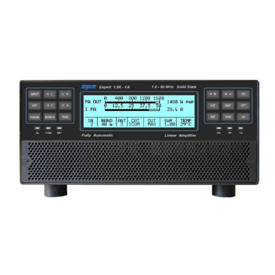
- Page 1 EXPERT 1.5K-FA 1.5KW SOLID STATE FULLY AUTOMATIC LINEAR AMPLIFIER USER’S MANUAL Rev. 2.0 Second series...
-
Page 2: Table Of Contents
INTERCONNECTION WITH THE TRANSCEIVER ................. 12 USE OF THE LINEAR AMPLIFIER ......................13 SO2R (Single Operator Two Radio ) ....................14 Band-Pass Filters Set “SPE BPF1” ....................15 QSK (Full Break-In) Operation ......................17 Tunable Antenna Control ........................ 17 Setting Up a Single Antenna for Reception ..................19 Two Possible Sets of Antennas (Bank A or Bank B) ................ - Page 3 User manual Expert Amp 1.5K-FA Ultrabeam cable: ..........................48 Serial connection to a standard PC RS-232 port for remoting use............48 TRANSCEIVER CONTROLLED BY PC ....................49 14.1 Icom CI-V Interface ......................... 49 RS232 Interface ..........................50 14.2 14.3 5V TTL Kenwood Interface ......................
-
Page 4: Important
This manual is valid only for the second series starting from the s / n 18xxxx180. All future software releases can also be used by the Expert 1.5K-FA first series whose features remain as in the manual rev.1.0. HOW TO READ THIS MANUAL This manual is divided into four main parts: •... -
Page 5: Precautions
User manual Expert Amp 1.5K-FA PRECAUTIONS Explicit definitions WORD DEFINITION Risk of danger of fire or electric shock to people. WARNING! Possible damage to the amplifier. Serious problems if not observed. Danger of fire or electric shock for the operator, NOTE: or damage to the equipment. - Page 6 User manual Expert Amp 1.5K-FA WARNING! DO NOT touch the amplifier with damp or wet hands. There will be a danger of electric shock. Avoid opening the amplifier before you have disconnected it from the mains supply plus wait at least 2 minutes for the electrolytic capacitors to complete their discharge. To clean the amplifier DO NOT use chemical agents like alcohol or benzene because the plastic surfaces could be damaged.
-
Page 7: Unpacking
User manual Expert Amp 1.5K-FA UNPACKING Remove the packing and carefully check the contents. Please look closely for the plastic pouch containing cables, fuses and connectors inside the box for your linear amplifier. It may be in the inside pocket of the canvas carrying bag. If you find any damage or if there are any parts missing, contact your distributor/dealer immediately. -
Page 8: Panel Description
User manual Expert Amp 1.5K-FA PANEL DESCRIPTION Front Panel 1) ON turns on unit. 2) OFF turns off unit when held down for three seconds. 3) DISPLAY toggles between display pages. switches output power between “MAX / MID / LOW“. 4) POWER 5) OP toggles back and forth between Standby/Operate modes. -
Page 9: Rear Panel
User manual Expert Amp 1.5K-FA Rear Panel 1) ANT connectors for four available antennas. 2) SO2R connector for SO2R operations. 3) INPUT connectors to connect two exciters. 4) FANS 5) IN 1 ALC, RELAY, CAT connectors for exciter 1. 6) IN 2 ALC, RELAY, CAT connectors for exciter 2. -
Page 10: General Information
User manual Expert Amp 1.5K-FA GENERAL INFORMATION (Read the specific chapters for more details). Power supply The amplifier uses a switching power supply that will automatically adapt to any AC voltage supply that is between 100 and 255 Vac and is 50 or 60 Hz. The main switch [I/O] is located on the rear panel. - Page 11 All modern transceivers have CAT control options. In older models, often the analog or digital information is sent from the Transceiver to the amplifier for band switching. In the SPE Expert 1.5K-FA, Thanks to an efficient frequency counter, the amplifier constantly monitors and verifies data coming from the transceiver.
-
Page 12: Interconnection With The Transceiver
User manual Expert Amp 1.5K-FA INTERCONNECTION WITH THE TRANSCEIVER The diagram shows the connections with one transceiver only. To connect the second transceiver, repeat the same connections used for “IN 1”, now using the port “IN 2“ connections. For ALC and RELAY connections, use a shielded cable (supplied) with RCA phono connectors. -
Page 13: Use Of The Linear Amplifier
User manual Expert Amp 1.5K-FA USE OF THE LINEAR AMPLIFIER Block diagram. The position of the contacts, as shown in the diagram, is the situation of the linear amplifier in the OFF state. The linear amplifier can be used in the following way: 1) OFF Only two direct connections are actuated: between INPUT 1 and ANT 1... -
Page 14: So2R (Single Operator Two Radio )
User manual Expert Amp 1.5K-FA SO2R (Single Operator Two Radio ) Operation of this kind is used during a contest in order to acquire a new multiplier, as quickly as possible. The following connections are needed (see the diagram): 1. INPUT 1 connected to the first transceiver (RTX1). -
Page 15: Band-Pass Filters Set "Spe Bpf1
In this case the amplifier is connected to a single transceiver (INPUT 1 or INPUT 2). "SPE BPF1 automatically selects the filter on the band to be used in the input where the transceiver is connected, while the other unrelated input is left unused. - Page 16 Expert Amp 1.5K-FA 2. Contest SO2R. In this case the amplifier is connected to two transceivers and two "SPE BPF1" in order to automatically select the right filters in the output of both the transceivers. These features can be possible, as well, with the simultaneous use of the unit "AMB-01”...
-
Page 17: Qsk (Full Break-In) Operation
The CAT is recommended, however, if the transceiver does not have the CAT or if it only has the "Band Data", the Expert 1.5K-FA will continue to drive the antenna with the frequency measured by the counter (data collected after the first transmission) . - Page 18 User manual Expert Amp 1.5K-FA The simplest possible configuration is a single tunable antenna according to the following diagram The link is configurable for any position (ANT 1,2,3,4) you want use. To select a tunable antenna, refer to the “TUN ANT” item on the main menu. After selection, on the display, next to the number of the antenna in use will appear a “t”.
-
Page 19: Setting Up A Single Antenna For Reception
In some cases it may be necessary to transmit with one antenna and receive with a more appropriate one. A unique feature allows the Expert 1.5K-FA to set a receiving antenna and to control its automatic switching after a transmission starts. -
Page 20: Predistortion
User manual Expert Amp 1.5K-FA Predistortion On the rear panel there is an SMA connector where the transmitted signal is attenuated by 60 dB (50 ohms). This signal can be used to connect an SDR transceiver with appropriate software in order to improve the IMD of the transmitted signal by 25 dBc or higher (depending on the software). -
Page 21: External Ground Connection
User manual Expert Amp 1.5K-FA EXTERNAL GROUND CONNECTION WARNING! Before connecting an external ground as described below, check with a qualified electrician that your national wiring codes permit such a connection. To reduce TVI, BCI and other RF problems it is best to connect the amplifier to a good RF ground. -
Page 22: Antenna
User manual Expert Amp 1.5K-FA ANTENNA Because this is a high-power amplifier, it is necessary to use properly rated antennas, connectors and feed line cables. Take special care with antennas using baluns and traps, because balun and/or trap warming can occur during periods of high-power transmission and a high SWR most likely will result. -
Page 23: Power Supply (Psu)
Expert Amp 1.5K-FA POWER SUPPLY (PSU) The power supply of the SPE Expert 1.5K-FA, unique in its category, is switching with a PFC (Power Factor Correction) that allows a drastic reduction of the harmonic components in the mains in accordance with IEC555-2, that consists of two sources. - Page 24 User manual Expert Amp 1.5K-FA You should observe all precautions in accordance with national legislation. The amplifier is supplied by a power supply that automatically adapts between 100 and 255 VAC, 47-63 Hz. In some particular cases, mains that are 100 to 120 VAC, the power in MAX may be reduced somewhat.
-
Page 25: Tuner (Atu)
User manual Expert Amp 1.5K-FA TUNER (ATU) The amplifier has an automatic tuner that handles load mismatches up to 5:1 VSWR (2.5:1 for 6 m). The amplifier contains a look-up table with all the permitted bands. For tuner management, antenna data and other working data are stored. Every band has a sub-band set, and for each of those, data related to the antenna and auto-ATU tuning is stored. - Page 26 User manual Expert Amp 1.5K-FA the tuner input where the load resistance is always constant (50 ohm). Do not expect external power meters to match the displayed power. It should be understood that an external measure of power might be lower depending on the matching attenuation.
-
Page 27: Protections / Alarms
User manual Expert Amp 1.5K-FA PROTECTIONS / ALARMS The SPE EXPERT 1.5K-FA has a sophisticated protection system that constantly monitors and controls the amplifier’s most important parameters. The main parameters are: Temperature of the heatsink: max. / min. voltage on the PA; max. PA current; SWR;... -
Page 28: Programming
User manual Expert Amp 1.5K-FA PROGRAMMING The three keys: [SET], [◄▲] and [▼►], allow programming the amplifier. They can be used in the following way: [SET] Use this key to open a menu page, to validate choices and to exit from a menu page. - Page 29 User manual Expert Amp 1.5K-FA This setup allows you to preset up to 2 antennas for the same band. The selected antennas can be switched using the [ANT] key while working either in the “OPERATE” or in the “STANDBY” mode and there is no transmission in progress.
- Page 30 User manual Expert Amp 1.5K-FA Make the CAT connection (read the “CONNECTIONS” - ELECRAFT chapter of this manual) and follow the same indications as for KENWOOD. Set your exciter to transmit a continuous RTTY or FM signal. Then press the [◄ L], [L ►], [◄ C], [C ►] keys until you obtain the minimum SWR.
-
Page 31: Initial Operation Of The Amplifier
User manual Expert Amp 1.5K-FA INITIAL OPERATION OF THE AMPLIFIER Before turning ON the amplifier, read this manual with care. The following preliminary operations are necessary: 1) Be sure that the mains voltage is within the proper range of the amplifier’s power supply requirements. - Page 32 User manual Expert Amp 1.5K-FA 2) To Set ANTENNAS: Press [SET] and open the “ANTENNA“ menu page. Assign an appropriate antenna output number for the desired band. If you don’t have an antenna for that band, select “NO“. To bypass the Tuner on a certain band and/or a certain antenna, just press the [TUNE] key, you will see a "b"...
- Page 33 User manual Expert Amp 1.5K-FA 4) Use of the Automatic Tuner (Internal ATU) To complete the programing it is necessary to match the antennas to the amplifier by operating the “TUNE“ function (read the “TUNER“ chapter of this manual). Select each band (with the proper antenna) and then program the tuner for all the sub-bands of every band.
-
Page 34: Operating
The use of both the ALC and CAT connections is highly recommended. If ALC is not used, SPE reminds you that it is better to lose a fraction of dB in transmitted power, by slightly reducing the driving power, than to over drive the amplifier and have a poor quality transmission. - Page 35 Speak into the microphone normally, then set the ” MIC GAIN” of the transceiver until the peak output power shown on the amplifier display is no more than 800W (MID) or 400W (LOW). SPE suggests to monitor your transmission closely to check that the “MIC. GAIN” setting is correct. e) FM: By monitoring your transmission you can easily get the correct emission by adjusting the.
-
Page 36: Connections
User manual Expert Amp 1.5K-FA CONNECTIONS 12.1 CAT Connector The pin outs are shown in the schematic below. The connections are the same for our 1K-FA, 1.3K-FA and 2K-FA amplifiers. pin n. pin name Description RX 232 Used on KENWOOD and YAESU transceivers for linking with a RS-232 connection. -
Page 37: Icom
User manual Expert Amp 1.5K-FA BAND DATA CODES Band BCD code Band Band 60 m. 30 m. 12 m. 160 m. 20 m. 10 m. 80 m. 17 m. 6 m. 40 m. 15 m. New connectors are supplied with the amplifier. Using the above information, an appropriate cable for your transceiver(s) may be constructed. -
Page 38: Kenwood
User manual Expert Amp 1.5K-FA 12.3 Kenwood CAT RS232 Interface RX 232 TX 232 RX 232 (RXD) (TXD) TX 232 RADIO CONNECTOR DB15 M The Radio connector could be DB-9 or DB-25 male connector or female connector (read the specific manual). In the manual, also verify if the RTS–CTS link is necessary. -
Page 39: Yaesu
User manual Expert Amp 1.5K-FA 12.4 Yaesu CAT RS232 Interface RX 232 TX 232 TX 232 (RXD) (TXD) RX 232 RADIO CONNECTOR DB15 M The radio connector may be a DB-9 or DB-25 male connector or female connector (read the specific manual). Verify from the manual if the RTS–CTS link is necessary. CAT 5V TTL Interface RX TTL TX TTL... -
Page 40: 15.5 Band Data Interface
User manual Expert Amp 1.5K-FA 15.5 BAND DATA Interface RADIO CONNECTOR BAND A BAND A BAND B BAND B BAND C BAND C BAND D BAND D DB15 M Using Band Data, instead of CAT, use the four digital signals (Band A, Band B, Band C, Band D) from the transceiver. -
Page 41: Alc With Flex-Radio
User manual Expert Amp 1.5K-FA ALC with Flex-Radio Since the analog ALC input is not usable in a Flex-Radio transceiver, its driving power must be manually programmed in order to avoid the EXPERT’s overdrive protection system intervention. Connect the CAT connector with the CAT connector of the Flex (read the specific Flex manual), in the menu page set FLEX as CAT, then set the power limits. -
Page 42: Transceivers Of Other Brands
A special link is not necessary as the internal amplifier frequency counter will measure the input frequency and will control the amplifier. Note: WARNING, SPE is not responsible for any failure resulting from misuse of hardware interfacing. INDEX Page. 42 of 89... -
Page 43: Other Connections
User manual Expert Amp 1.5K-FA OTHER CONNECTIONS On the CAT connector, in addition to the CAT signals, the ALC and RELAY controls are the same as the RCA phone connectors. REMOTE ON, /TX–INH, TX–INH are also available. If you use this connector to connect the ALC and RELAY lines, the separate RCA phono cables are not recommended. -
Page 44: 13.3 Connections Tx-Inh, / Tx-Inh
All modern transceivers have a delay before the transmission to allow the linear to stabilize their relays avoiding damage to the contacts as a result of "Hot Switching". The Expert 1.5K-FA has a settling time of less than 6 msec. compatible with all modern transceivers (see the manual of the transceiver). -
Page 45: Tx-Inh Link
User manual Expert Amp 1.5K-FA / TX-INH Link Note: WARNING, SPE is not responsible for any failure resulting from misuse of hardware interfacing. INDEX Page. 45 of 89... -
Page 46: 13.4 Aux Connector
1 = RX state + 12 Vcc OUT + 12 VDC 0.2 A max. Each output is an open collector. Note: WARNING, SPE is not responsible for any failure resulting from misuse of hardware interfaces. INDEX Page. 46 of 89... -
Page 47: 13.5 Port Connector
User manual Expert Amp 1.5K-FA 13.5 PORT Connector This connector provides: a) Data about the ANT port in use (each output is open collector). b) RS 232 port for connection to a controller of a tunable antenna. c) RS 232 port for remoting use (as an alternative of USB port). Pin n. -
Page 48: Ultrabeam Cable
DB-9/M DB-9/F TX_232 / 7 2 / RX_PC RX_232 / 8 3 / TX_PC GND / 5 5 / GND Note: WARNING, SPE is not responsible for any failure resulting from misuse of hardware interfaces. INDEX Page. 48 of 89... -
Page 49: Transceiver Controlled By Pc
If the transceiver is controlled by a PC using the CAT utility, the link with the amplifier can be made as described in the following paragraphs. Note: BEWARE, SPE assures only the direct connection between the Linear and transceiver. The use of external control software could create malfunctions that must... -
Page 50: Rs232 Interface
User manual Expert Amp 1.5K-FA 14.2 RS232 Interface KENWOOD OR YAESU RADIO CONNECTOR RS232 RX 232 TX 232 RS232 PC CONNECTOR DB15 M 14.3 5V TTL Kenwood Interface KENW OOD RADIO CONNECTOR RX TTL TX TTL KEN TTL TTL INTERFACE DB15 M INDEX Page. -
Page 51: Ttl Yaesu Interface
User manual Expert Amp 1.5K-FA 14.4 5V TTL Yaesu Interface YAESU RADIO CONNECTOR RX TTL TX TTL TTL INTERFACE DB15 M Note: WARNING, SPE is not responsible for any failure resulting from misuse of hardware interfaces. INDEX Page. 51 of 89... -
Page 52: Use Of The Usb / Rs232 Ports
User manual Expert Amp 1.5K-FA USE OF THE USB / RS232 PORTS Through the USB / RS232 ports on the rear panel it is possible to interface the amplifier with a PC. Two features are possible: a) To remote the linear. b) To download newer and updated firmware releases. -
Page 53: Remote Control
See “Appendix 1” on this manual. 15.2 Download The sophisticated design of the Expert 1.5K-FA allows you to download any new versions of Software from the following site: www.linear-amplifier.com Where a software for blind people is also freely available as well as the "Application Programmer’s Guide"... -
Page 54: Maintenance
Expert Amp 1.5K-FA MAINTENANCE The Expert 1.5K-FA linear amplifier does not need internal maintenance because it has a cover without ventilation holes. Since HV tubes are not used, the natural attraction to dust is eliminated. Therefore the user only needs to periodically check and clean the air filter on the front panel. -
Page 55: Characteristics / Specifications
User manual Expert Amp 1.5K-FA CHARACTERISTICS / SPECIFICATIONS - The smallest in its class: Built-in Power supply and Automatic Antenna Tuner. Dimension: L 28, H 12, P 38 cm ( 11.02” W, 4.72” H, 14.96” D ) connector included. Approx. weight about 9,5 Kg (20.9 lbs). - The most technologically advanced in the world: Two powerful CPUs are used. - Page 56 User manual Expert Amp 1.5K-FA - Very clean and low distortion output: Spurious emissions FCC/CE compliant. 3rd order distortion (two tone test) from -30 dB to -35 dB ( typ. ). - Input 50 ohm always perfectly matched: The same protection is realized in two different ways: Via hardware circuits (HW) to assure great speed.
-
Page 57: Diagnostics
User manual Expert Amp 1.5K-FA DIAGNOSTICS. During normal operation, the sophisticated monitoring system continuously monitors several measurements directly acquired from internal test-points. When a dangerous situation occurs, a “serious” alarm message is raised and the amplifier is switched from OPERATE to STANDBY. The user can either restore immediately the Main Display Page by pressing the [DISPLAY] key or wait for the visual alarm time-out expiration (about 10 seconds). -
Page 58: Table
User manual Expert Amp 1.5K-FA TABLE BAND TABLE, SUB-BAND, CENTRAL FREQUENCY SUB-BAND [ 0] 1785 [ 1] 1795 [ 2] 1805 [ 3] 1815 [ 4] 1825 [ 5] 1835 [ 6] 1845 [ 7] 1855 [ 8] 1865 [ 9] 1875 [ 10] 1885 [ 11] 1895 160 m... -
Page 59: Appendix 1 - Remote Control
User manual Expert Amp 1.5K-FA APPENDIX 1 - REMOTE CONTROL Overview: With reference to that described in Section 15. “USE OF THE USB / RS 232 PORTS”, this appendix contains the following sections: SW installation Term_1.5K_USB.exe usage Term_1.5K_232.exe usage Firmware update The host PC must have the minimum of a correctly installed Windows XP operating system, or a newer release of Microsoft’s operating system such as Windows Vista, Windows 7, with a typical minimum of RAM and hard disk space. - Page 60 User manual Expert Amp 1.5K-FA The default destination folder is good for this use, so complete this operation by using the Extract key as shown in the picture above. This step reveals a new uncompressed folder, having the same name of the original compressed one contained in the installation package.
- Page 61 User manual Expert Amp 1.5K-FA Once opened, the C:tmp\Term_1.5K_Package_1_0 folder will show the following contents: Where: FT_232_RL is a folder containing the USB drivers and an automatic installation program, which must be run just once to prepare the operating environment which sorts out everything needed, such as the USB drivers and their support files on the Windows host system.
- Page 62 The next step is to connect the PC and the EXPERT 1.5K-FA by using the equipped USB cable and waiting for the identification of the newly created USB connection.
-
Page 63: Term_1.5K_Usb.exe Usage
User manual Expert Amp 1.5K-FA The USB port installation and its setting is now complete. Now that this fundamental step has been successfully completed, the application Term_1.5K_USB.exe remote control application can be launched. this purpose back-step starting uncompressed folder Term_1.5K_Package_1_0 must be performed and double-click on the application filename, as indicated in the picture below Note: Do not forget that Term_1.5K_USB.exe requires full accessibility to the ftd2xx.dll... - Page 64 This is the main window of Term_1.5K_USB.exe application. It is a realistic reproduction of the EXPERT 1.5K-FA LCD display, and it is also equipped with a pop-up virtual keypad having almost the same look and feel as the real keypad placed on the front panel of the linear amplifier.
- Page 65 User manual Expert Amp 1.5K-FA The View menu also contains five items related to the application window size presets which can be either selected by the menu itself or by their equivalent [F1 … F5] shortcut keys. Feel free to test all the View menu options in order to find an optimal and comfortable vision of the display main window.
- Page 66 Similarly, all the other virtual keypad keys perform the same actions as their equivalent mechanical keys forming the real front panel keyboard of the EXPERT 1.5K-FA. The View menu is also equipped with the useful Home… and Park… items which have been specially designed to allow an automatic repositioning of the application along the PC desktop area.
- Page 67 User manual Expert Amp 1.5K-FA The Basic keypad... item in View menu allows you to set to a reduced-size keypad, having fewer keys than the complete keypad, which could be useful when no setting actions are required on the linear amplifier. Note: The keypad types, both Full and Basic, are certainly very useful since they both can be directly accessed using the mouse pointer.
- Page 68 User manual Expert Amp 1.5K-FA (*) Please bear in mind that the [OFF] command as accessed from the virtual keypad or by shortcut key, that it always asks for a confirmation, to its amplifier shutdown operation, by showing the dialog form below: INDEX Page.
- Page 69 Preliminary programming for “ID string property” with Term_1.5K_USB.exe . This special setting, based upon an easy “self-learning” procedure, must be performed once, however only after having put the Expert 1.5K-FA into an OFF-LINE state. Then, select File/Configure USB connection... from the main menu as shown in the picture...
- Page 70 User manual Expert Amp 1.5K-FA A dialog window will pop up: Press the Acquire ID string key, marked in the picture above, in order to start the ID string characters acquisition process across the USB data-link. This is a guided self- learning procedure.
- Page 71 User manual Expert Amp 1.5K-FA The following pop-up notification message will be displayed when a successful connection via USB occurs: The picture above shows the acquisition report of a device that its ID String Property is A400F1MZ. As explained earlier, this parameter is unique to any given specific chip, so it doesn’t allow duplicates among other components from the same manufacture.
- Page 72 User manual Expert Amp 1.5K-FA Once the user validates the data acquisition, by pressing the OK key as marked in the picture above, the Term_1.5K_USB.exe internal database will be properly updated and as confirmation, the application status bar will be updated, as shown in the following picture: When the above described steps are completed, Term_1.5K_USB,exe will only be able to recognize and address the EXPERT linear amplifier whose unique ID String matches...
- Page 73 User manual Expert Amp 1.5K-FA A last note. If, for whatever reason, all the selective addressing capabilities are no longer needed, to open a connection to an EXPERT linear thru its USB link, they can be temporarily disabled. The next operation is quite easy to perform. After having recalled the Configure USB connection dialog box, using its specific item contained into the File menu, using your mouse click on the Enable ID Addressing option, as shown in the following picture, and confirm this entry using the OK button.
-
Page 74: Term_1.5K_232.Exe Usage
User manual Expert Amp 1.5K-FA 20.3 Term_1.5K_232.exe usage To start running the Term_1.5K_232.exe application, it is necessary to go back into the Term_1.5K_Package_1_0 uncompressed folder and select the related filename as shown in the picture below: A suggestion is to create a link to the application and place it on the Windows desktop. A double-click using the left-button of the mouse on the application icon should render a result as the one shown in the following picture: The very first time Term_1.5K_232.exe is launched, a notifying pop-up message, like... - Page 75 The above menu item makes it possible to access the following dialog box, which allows a direct setting of the desired COMx serial port for connecting to the EXPERT 1.5K-FA. If the number of an unused COM is unknown, proceed as the following page.
- Page 76 User manual Expert Amp 1.5K-FA With all your serial resources properly connected, proceed to the Control Panel >>> Hardware and Sound >>> Device Manager and choose a serial COM listed in the hardware configuration that is not used by other applications. In the case that USB-to-RS232 serial converters are being used, as shown in the picture above, please proceed, as explained below, to check all the COM ports polled by the system.
- Page 77 User manual Expert Amp 1.5K-FA In that case, use the detached COM port ID to properly set the Virtual Com Port dialog box, as shown in the picture below, and then reconnect the serial adapter so that it can be accessed by the application... The available selection range spans thru the [COM1…COM256] set, which can be accessed using the framed slider-control placed above the OK and CANCEL keys.
- Page 78 The reason for this is because it is a permanent setting, which is stored into a private data-base system, and will be recalled by the application whenever needed. On the EXPERT 1.5K-FA side, the baud-rate is automatically synchronized by the data- pattern being sent to it by Term_1.5K_232.exe upon any query to the linear.
-
Page 79: Remote On/Off Using Rs-232
User manual Expert Amp 1.5K-FA Remote ON/OFF using RS-232. With this new software release, the [ON] and [OFF] keys are fully enabled and work the same way as they work on the USB version of the application. However, there is a small technical detail to take into account about the [ON] key's behaviour. - Page 80 User manual Expert Amp 1.5K-FA A note about the DTR-link behaviour. Even though this circuit seems to work correctly when driven by software, it could cause unexpected switching-on of a connected linear amplifier having its rear panel's mains- switch enabled, when the linked PC re-boots or when an external serial device (e.g. a USB to serial adaptor...) is physically connected.
-
Page 81: Firmware Update
Switch the linear on leaving it set to the STANDBY mode during the firmware updating. Under these conditions the File\Firmware update menu item becomes active and, after being selected, it sets the EXPERT 1.5K-FA into its firmware update mode (FIRMWARE UPDATE PROCEDURE). - Page 82 User manual Expert Amp 1.5K-FA After then a dialog box pops-up, and the user must select a proper firmware package, that data will be sent to the linear amplifier to update all its embedded functions Observe the example in the picture below where a firmware package file named 1.5k_01_01_17_A.pk3 has been selected: After the necessary confirmation by the user for validating the procedure, the EXPERT 1.5K-FA switches its display off as the updating is being transferred to the...
- Page 83 User manual Expert Amp 1.5K-FA The main steps of firmware update procedure are below: • Checking and validation of updating firmware package • A physical data transmission of the new firmware from the PC to the linear amplifier INDEX Page. 83 of 89...
- Page 84 User manual Expert Amp 1.5K-FA • A final validation for the completed firmware update And as the last action, after a successful firmware update, the linear amplifier performs a general auto-restart operation. Then after, full control of the updated device is restored to both local and remote operations.
-
Page 85: General Restore
User manual Expert Amp 1.5K-FA GENERAL RESTORE A System General Restore can be performed by pressing the [INPUT] and the [OFF] keys together for at least one second. This operation is only possible from the linear amplifier front-panel physical keyboard. The linear amplifier will switch off with a self-explaining system message. -
Page 86: Warranty Term
In order to not invalidate the warranty service, the original Purchaser must complete the warranty registration card, and send it to SPE no more than 30 days from the date of purchase. Unless otherwise agreed, the products will be delivered ex-works from the factory of the seller. - Page 87 User manual Expert Amp 1.5K-FA 1. Improper maintenance or repair by persons not authorised by SPE to carry out such work, including the installation of parts or accessories that do not conform to the quality and specifications of the original parts.
-
Page 88: Repair Form
User manual Expert Amp 1.5K-FA REPAIR FORM MODEL ..... SERIAL NUMBER ....DATE ....CONNECTION STATE AT THE MOMENT OF THE BREAKDOWN TRANSCEIVER MODEL . - Page 89 User manual Expert Amp 1.5K-FA s.r.l. Via di Monteverde, 33 00152 Rome (Italy) Tel. +390658209429 Fax. +390658209647 E-mail: info@linear-amplifier.com Website: http://www.linear-amplifier.com INDEX Page. 89 of 89...
Need help?
Do you have a question about the EXPERT 1.5K-FA and is the answer not in the manual?
Questions and answers
Display shows: "CAT ERROR" CAN NOT RESOLVE?
"CAT ERROR" on the SPE EXPERT 1.5K-FA display means there is a wrong hardware or software setting of the CAT (Computer Aided Transceiver) interface. To resolve it, check and correct the CAT connection settings, including the correct COM port and proper configuration in both the transceiver and amplifier. Ensure that the cable used is appropriate and properly connected.
This answer is automatically generated