
Subscribe to Our Youtube Channel
Summary of Contents for Gables Engineering G7490-07
- Page 1 Pilot’s Guide G7490-07 Flight ID / ATC / TCAS G7490-07 Pilot’s Guide Rev 01 COPYRIGHT © Gables Engineering, July 28, 2004 Author: Sylvain Cloutier (scloutie@gableseng.com) (305) 774-4400 Fax: (305) 774-4465...
- Page 2 All rights reserved. No part of this manual may be reproduced, stored in a retrieval system or transmitted in any form or by any means, mechanical, photo-copying, electronic, or otherwise, without the prior written permission of Gables Engineering, 247 Greco Ave, Coral Gables, FL 33146 G7490-07 Pilot’s Guide Rev 01...
-
Page 3: Table Of Contents
Pilot’s Guide G7490-07 TABLE OF CONTENTS G7490-07 (Flight ID/ATC/TCAS) System Description............. 1 Panel Controls and Indicators ..................1 XPNDR (Transponder) Select Knob ................ 2 IDENT (Identification) Button ................... 2 XPNDR (Transponder) FAIL Indicator ..............2 FID (Flight Identification) Indicator ................2 ATC (Air Traffic Control) Indicator................ - Page 4 Pilot’s Guide G7490-07 Intentionally left blank G7490-07 Pilot’s Guide Rev 01 COPYRIGHT © Gables Engineering, July 28, 2004...
-
Page 5: G7490-07 (Flight Id/Atc/Tcas) System Description
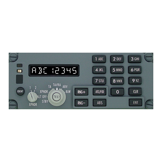
G7490-07 G7490-07 (Flight ID/ATC/TCAS) System Description This control panel is capable of controlling two Dual Mode-S transponders with TCAS and Flight ID capabilities. This guide describes the operation of the G7490-07 Flight ID/ATC/TCAS control panel Panel Controls and Indicators This section describes the control functions of the G7490-07 Flight ID/ATC/TCAS control panel. -
Page 6: Xpndr (Transponder) Select Knob
Press and hold the ABS button to momentarily change the altitudes shown on the TCAS display from “relative” to “absolute”. See “Panel Operation” below for more details. G7490-07 Pilot’s Guide Rev 01 COPYRIGHT © Gables Engineering, July 28, 2004 Page 2 of 17... -
Page 7: Rng+ And Rng- Buttons
2700 feet above and 2700 feet below your aircraft (+2700 ft and -2700 ft relative to your aircraft). G7490-07 Pilot’s Guide Rev 01 COPYRIGHT © Gables Engineering, July 28, 2004 Page 3 of 17... -
Page 8: Abv
Refer to Figure 4, Figure 5, Figure 6, and Figure 7 for examples. If the selected side is not energized (power loss), the XPNDR FAIL indicator illuminates and the display is blanked. G7490-07 Pilot’s Guide Rev 01 COPYRIGHT © Gables Engineering, July 28, 2004 Page 4 of 17... - Page 9 Module 1 and Module 2 Figure 7 - Test sequence with the XPNDR Select Knob set to “2” and communication problem between Module 1 and Module 2 G7490-07 Pilot’s Guide Rev 01 COPYRIGHT © Gables Engineering, July 28, 2004 Page 5 of 17...
-
Page 10: Setting The Atc Code
NOTE: If you press the IDENT button while the code entered is incomplete (if the code has less than 4 digits), the incomplete code is not transmitted and the previously transmitted code will re-appear on the display. G7490-07 Pilot’s Guide Rev 01 COPYRIGHT © Gables Engineering, July 28, 2004 Page 6 of 17... -
Page 11: Setting The Flight Id
For example, to enter VX you must press the “8 VWX” button twice (for “V”), wait 1.5 seconds, and then press the “8 VWX” button four times (for ‘X). Refer to Figure 11 for an example. G7490-07 Pilot’s Guide Rev 01 COPYRIGHT © Gables Engineering, July 28, 2004 Page 7 of 17... - Page 12 Pilot’s Guide G7490-07 Figure 10 – Alphanumeric sequence of keypad buttons G7490-07 Pilot’s Guide Rev 01 COPYRIGHT © Gables Engineering, July 28, 2004 Page 8 of 17...
- Page 13 Pilot’s Guide G7490-07 Figure 11 – Entering the same alpha character twice G7490-07 Pilot’s Guide Rev 01 COPYRIGHT © Gables Engineering, July 28, 2004 Page 9 of 17...
- Page 14 (occurs after 1.5 seconds). Refer to Figure 13 for an example. There is no need to wait 1.5 seconds if you press a different button. G7490-07 Pilot’s Guide Rev 01 COPYRIGHT © Gables Engineering, July 28, 2004 Page 10 of 17...
- Page 15 2 and paragraph 3 above). See Figure 14. If you enter a wrong digit, momentarily press the CLR button to go back one position. G7490-07 Pilot’s Guide Rev 01 COPYRIGHT © Gables Engineering, July 28, 2004 Page 11 of 17...
-
Page 16: Accepting The Flight Id
Before the Flight ID can be transmitted, you must press the ENT button. The FID indicator stops flashing when you press the ENT button. Refer to Figure 15. Figure 15 – Accepting the Flight ID G7490-07 Pilot’s Guide Rev 01 COPYRIGHT © Gables Engineering, July 28, 2004 Page 12 of 17... -
Page 17: Selecting The Altitude Display Mode
(+2700 ft and -9900 ft relative to your aircraft). Refer to Figure 16 for a visual representation of the “Above (ABV), Normal (N) and Below (BLW)” altitude bands of the TCAS system. G7490-07 Pilot’s Guide Rev 01 COPYRIGHT © Gables Engineering, July 28, 2004 Page 13 of 17... -
Page 18: Selecting The Tcas Display Range
RNG- button. The RNG- button has no effect once the display shows “RANGE 5”. Figure 17 shows the sequence when changing the TCAS display range. G7490-07 Pilot’s Guide Rev 01 COPYRIGHT © Gables Engineering, July 28, 2004 Page 14 of 17... - Page 19 Pilot’s Guide G7490-07 (Assuming current range setting is 5 nm) Figure 17: Selecting TCAS Display Range with RNG buttons G7490-07 Pilot’s Guide Rev 01 COPYRIGHT © Gables Engineering, July 28, 2004 Page 15 of 17...
-
Page 20: Showing Absolute Altitudes On The Tcas Display
A lamp test can only be initiated with a remote switch. The lamp test cannot be initiated through the front controls of the G7490-07 control panel. When a Lamp Test is initiated through a remote switch, all the display segments and indicators will illuminate. The display segments and indicators will illuminate until the Lamp Test is stopped but no longer than 2.5 minutes. - Page 21 Pilot’s Guide G7490-07 Intentionally left blank G7490-07 Pilot’s Guide Rev 01 COPYRIGHT © Gables Engineering, July 28, 2004 Page 17 of 17...
- Page 22 Gables Engineering, Inc. 247 Greco Avenue Coral Gables, Florida 33146 Telephone 305.774.4400 Facsimile 305.774.4465 “The Leader in Avionic Controls and Systems Since 1946”...
Need help?
Do you have a question about the G7490-07 and is the answer not in the manual?
Questions and answers