Table of Contents
Advertisement
Quick Links
REMOTE FIRING DEVICE
OPERATION MANUAL
The information contained in this document is subject to change
without notice. In no event shall Rothenbuhler Engineering
Company be liable for errors contained herein or for special,
indirect, or consequential damages or injuries of any nature
resulting from use of information in this document.
ROTHENBUHLER ENGINEERING
P.O. BOX 708
524 RHODES ROAD
SEDRO WOOLLEY, WA 98284
1678-A16 {Draft}
5/12/2011
©2011 Rothenbuhler Engineering
All Rights reserved
Advertisement
Table of Contents

Summary of Contents for Rothenbuhler Engineering 1678 REMOTE FIRING DEVICE
- Page 1 REMOTE FIRING DEVICE OPERATION MANUAL The information contained in this document is subject to change without notice. In no event shall Rothenbuhler Engineering Company be liable for errors contained herein or for special, indirect, or consequential damages or injuries of any nature resulting from use of information in this document.
-
Page 2: Special Notice
LIMITED WARRANTY The manufacturer warrants the Model 1678 Remote Firing Device (RFD) to be free of defects in workmanship or materials for the period of one year from the date of purchase. In the event any RFD or component thereof is shown to be defective in workmanship or materials within one year, the system or component will be repaired or replaced without charge by the manufacturer at the manufacturer’s place of business. -
Page 3: Fcc Notice
FCC NOTICE This device complies with Part 15 of the FCC regulations. Operation is subject to the following two conditions: (1) That this device may not cause harmful interference, and (2) this device must accept any interference received, including interference that may cause undesired operation. - Page 4 Conformément à la réglementation d'Industrie Canada, le présent émetteur radio peut fonctionner avec une antenne d'un type et d'un gain maximal (ou inférieur) approuvé pour l'émetteur par Industrie Canada. Dans le but de réduire les risques de brouillage radioélectrique à l'intention des autres utilisateurs, il faut choisir le type d'antenne et son gain de sorte que la puissance isotrope rayonnée équivalente (p.i.r.e.) ne dépasse pas l'intensité...
-
Page 5: Table Of Contents
TABLE OF CONTENTS Chapter Page SPECIAL NOTICE ......................II WARNING TO USERS AND AFFECTED PERSONS ............ II LIMITED WARRANTY ....................II FCC NOTICE ......................... III RADIATION HAZARD WARNING................. III CANADA........................III TABLE OF CONTENTS....................V LIST OF ILLUSTRATIONS..................VIII SAFETY INFORMATION....................X INTRODUCTION ....................1 1.1. - Page 6 2.9. Antenna Assembly ..................21 2.10. Carrying Case ..................... 22 2.11. Vent operation ..................... 25 2.12. Antenna / Battery Charger Connector ............26 2.13. Connector Dust Cover Operation ..............27 SYSTEM SPECIFICATIONS................28 3.1. Radio ......................28 3.2. Physical ......................29 3.3.
- Page 7 6.4. Maintenance & Equipment Storage ..............44 BASIC TROUBLESHOOTING IN THE FIELD ........... 45 7.1. Remote Units ....................45 7.2. Mini Controller Unit ..................45 7.3. Remote Shock Tube Initiator................45 OPTIMIZING RANGE..................47 TEST BOX......................52 9.1. Test Box Descriptions ..................52 9.2.
-
Page 8: List Of Illustrations
LIST OF ILLUSTRATIONS Figure 2-1 RFD 4-Remote Case System................. 6 Figure 2-2 Mini Controller Unit ..................7 Figure 2-3 Mini Controller Isometric View with Antenna ..........12 Figure 3-1 Electric Remote Unit ..................13 Figure 3-2 Electric Remote Unit Angled View ............... 15 Figure 3-3 Remote Shock Tube Initiator (RSTI) ............ - Page 9 Figure 10-1 Test Box..................... 52 1678 RFD OPERATION MANUAL {DRAFT}...
-
Page 10: Safety Information
SAFETY INFORMATION The following are WARNINGS and CAUTIONS, contained throughout this manual and are repeated here for emphasis. All personnel engaged in the handling, firing, and storage of the system covered in this manual must fully understand these WARNINGS and CAUTIONS, and procedures by which hazardous conditions are to be reduced or eliminated. - Page 11 Ensure that blasting caps are not connected to any of the Remote WARNING Units during bench testing. This is a sensitive electronic radio system and it may be damaged. WARNING Do not use the Mini Controller Unit within 100 feet (30 meters) of WARNING explosives, blasting caps, or wires leading to them.
- Page 12 CAUTION Do not use any component that is damaged, suspected of being damaged, or is not able to operate as designed. The safety of the operation could be compromised. 1678 RFD OPERATION MANUAL {DRAFT}...
-
Page 13: Introduction
1. INTRODUCTION 1.1. PURPOSE 1.1.1. The primary purpose of this manual is to provide descriptive information, operational information, instructions in assembly, and instructions in testing and preparation for operational or training use of the Remote Firing Device (RFD). 1.1.2. The Remote Firing Device (RFD) is used to activate electric and non-electric detonator devices. - Page 14 operation range from -15 ºF to +140 ºF (-26 ºC to +60 ºC). 1678 RFD OPERATION MANUAL {DRAFT}...
-
Page 15: Maintenance
1.3. MAINTENANCE 1.3.1. Batteries within the RFD require periodic charging and discharging to maintain health and service life. 1.3.2. The battery packs within the RFD should be replaced every 3 years or 300 charge cycles, whichever comes first. Battery packs can be replaced by the user following strict procedures to maintain case sealing. -
Page 16: Introduction To Rfd System Components
2. INTRODUCTION TO RFD SYSTEM COMPONENTS 2.1. SYSTEM 2.1.1. The RFD is a battery powered, hand held, radio remote controlled system to be used on land as a primary firing mechanism to detonate explosive charges. The RFD system consists of a Mini Controller Unit and up to four Remote Units (any combination for Electric Remotes and RSTIs up to a total of four). - Page 17 Table 2-1 RFD 4-Remote Case System Figure Index No. Description Units per System Figure 2-2 Mini Controller Unit Figure 2-2 Remote Unit, Electric Up to 4* Figure 2-2 Remote Unit, RSTI Up to 4* Figure 2-2 Battery Charger See note ** Figure 2-2 Antenna Assembly One per Unit...
-
Page 18: Figure 2-1 Rfd 4-Remote Case System
Figure 2-1 RFD 4-Remote Case System 1678 RFD OPERATION MANUAL {DRAFT}... -
Page 19: Mini Controller Unit
2.2. MINI CONTROLLER UNIT 2.2.1. Figure 2-2 shows the external features of the Mini Controller Unit. The unit is sealed at the manufacturer and/or service depot and should not be opened during field activity. Figure 2-2 Mini Controller Unit 2.3. MINI CONTROLLER UNIT SWITCH OPERATION 2.3.1. - Page 20 2.3.2. Power ON Self Test: Upon installing the antenna and pressing the “ON” switch, a rigorous self test is initiated. If a failure of the self test occurs, it will not be possible to activate the unit. The unit must be returned to the Manufacturer for service. Do not attempt to use a failing unit.
- Page 21 2.3.7. Disarm the Remote Unit: Depress the “DISARM” switch. The Mini Controller Unit will transmit the Disarm command to selected Remote Units. Selected Remote Units will internally discharge their firing capacitor. Selected Remote Units that receive the Disarm command will become disarmed within 3 seconds of receiving the command.
-
Page 22: Mini Controller Unit Display Operation
• Depress the switches for the Remote Units that will not be fired initially. • Depress the “FIRE” switch. Only Remote Units still selected will fire. • Depress the switches for the Remote Units that were just fired. • Depress the switches for Remote Units to be fired next. •... - Page 23 2.4.6. Remote Unit Armed: A red light next to each of the “1” though “4” switches is used to indicate when the corresponding Remote Unit is armed. The ARMED light for selected Remote Units will flash after the Arm command is sent to the selected Remote Units.
-
Page 24: Figure 2-3 Mini Controller Isometric View With Antenna
Figure 2-3 Mini Controller Isometric View with Antenna 2.4.13. Figure 2-3 shows an isometric view to further illustrate the exterior features of the Mini Controller. 2.4.14. Manual Air Vent: A manual vent is located on top of the unit. The vent is used to relieve any internal pressure that has accumulated within the unit as a result of temperature or altitude. -
Page 25: Electric Remote Unit
2.5. ELECTRIC REMOTE UNIT 2.5.1. Figure 2-4 shows the external features of the Electric Remote Unit. The unit is sealed at the manufacturer or service depot and should not be opened during field activity. Figure 2-4 Electric Remote Unit 2.5.2. Power ON Self Test: Immediately after the Electric Remote is turned on by installing the Antenna, a rigorous self-test is performed. - Page 26 2.5.3. Safe Separation Time: Upon the installation of the Antenna, a safe separation countdown timer is initiated. During the safe separation time, the SAFE and ARMED lights will be on steady, while the ON light blinks rapidly. During the safe separation time, the unit will not accept any radio commands (i.e.
- Page 27 Figure 2-5 Electric Remote Unit Angled View 2.5.9. Binding Posts: The Binding Posts located on top of the Electric Remote Unit allow the firing cable to attach to the firing terminals. The insulation at the ends of the firing cable must be removed prior to attachment. One at a time, depress the top of the binding posts and insert a leg of the firing cable.
-
Page 28: Remote Shock Tube Initiator (Rsti)
2.5.12. System Configuration Label: The System Configuration Label contains information related to the settings of the unit within the system it operates. The information displayed on this label may be considered semi-permanent. 2.5.13. Model, Serial Number, FCC ID, and IC Label: The information displayed in this label is permanently assigned by the factory. - Page 29 Figure 2-7 RSTI Angled View with Shock Tube Spark Tip 2.6.3. Figure 2-7 shows the installation of the Shock Tube Firing Tip onto the Firing Terminals on the RSTI. 1678 RFD OPERATION MANUAL {DRAFT}...
- Page 30 Figure 2-8 Shock Tube Tip 2.6.4. Figure 2-8 shows the installation of the shock tube onto the shock tube firing tip when preparing for use. Care should be taken when handling the shock tube to prevent the incursion of debris or moisture into the tube. •...
-
Page 31: Position Battery Charger
2.7. 3 POSITION BATTERY CHARGER 2.7.1. Figure 2-9 shows the 3 Position Charger that is used in some of the 1678 RFD Kits. The 3 Position Charger provides a basic 3 to 4 hour recharge for up to three RFD units (e.g. one Mini Controller and two Remotes). It may be stored and used within the 1678 case/foam, or it can be stored and used as a stand-alone device. - Page 32 2.8.2. Serial Communications Port: The Test Box can be connected to a serial RS-232 port on a host PC. The connection can be used to log the results of the tests performed. The serial communications port is also used when performing parameter changes.
-
Page 33: Antenna Assembly
• Battery Temperature and Charge Cycle Count • Fire Count • Battery voltage of unit under test while the battery is being loaded down. • Electric Remote Units and RSTIs under test are armed and fired. The firing voltages are displayed. 2.8.5. -
Page 34: Carrying Case
Figure 2-11 Antenna Assembly 2.10. CARRYING CASE 1678 RFD OPERATION MANUAL {DRAFT}... - Page 35 2.10.1. Figure 2-12 Carrying Case shows the full system Carrying Case and Figure 2-13 Carrying Case (Half Case)shows the Carrying Case (Half-Case). Shown are the physical sizes of the Carrying Cases and a view of the storage location for System assemblies in the Carrying Cases.
- Page 36 Figure 2-13 Carrying Case (Half Case) 1678 RFD OPERATION MANUAL {DRAFT}...
-
Page 37: Vent Operation
2.11. VENT OPERATION 2.11.1. In Figure 2-14, the unit vents shown are manually operated and relieve internal pressure due to heat and altitude. When the vent is closed, it will not leak in 100 feet of water (30 meters) or up to 30,000 feet (9,100 meters) in altitude. CAUTION Unequal air pressure inside the Mini Controller Unit may affect the operation of membrane switch keypad. -
Page 38: Antenna / Battery Charger Connector
2.12. ANTENNA / BATTERY CHARGER CONNECTOR 2.12.1. Figure 2-15 shows the connections when using the 3-Position Charger. 2.12.2. The chargers do not discriminate between Mini Controller units and Remote units; any unit may be connected to any charge connector. Figure 2-15 3-Position Charger Connection 1678 RFD OPERATION MANUAL {DRAFT}... -
Page 39: Connector Dust Cover Operation
2.13. CONNECTOR DUST COVER OPERATION 2.13.1. In Figure 2-16, the Mini Controller Unit and Remote Unit have an antenna / battery charger connector dust cover that protects the connector pins from shorting out and damage when the Antenna Assembly or Battery Charger Assembly is not connected. -
Page 40: System Specifications
3. SYSTEM SPECIFICATIONS 3.1. RADIO CARRIER 150 - 174 MHz OPERATING -30ºC to 60ºC FREQUENCY TEMPERATURE -22ºF to 140ºF RANGE -26ºC to 60ºC (RSTI) -15ºF to 140ºF (RSTI) Certified <freq. diff. 800 HZ (±400) MINI CONTROLLER ELECTRIC UNIT & TEST BOX REMOTE &... -
Page 41: Physical
3.2. PHYSICAL Mini Controller Unit Electric Remote Unit and RSTI SIZE (w/out 8H x 3W x 2.5D SIZE (w/out 6H x 3W x 2.5D antenna) (in) antenna)(in) SIZE (w/out 20.32H x 7.62W x SIZE (w/out 15.24H x 7.62W x antenna) (cm) 6.35D antenna)(cm) 6.35D... -
Page 42: Timing
Remote Unit FIRE time:* 20 Milliseconds *This is the delay after the Remote Unit receives the command signal from the Mini Controller Unit to Fire. **The system’s Arm Time Period is factory set. Consult Rothenbuhler Engineering for details. 3.5. DETONATE OUTPUT The Remote Unit detonation output pulse is from a 2200 microfarad capacitor charged to 50 volts. -
Page 43: System Identification
Pulse Voltage Level: 2,500 VDC (typical), 2,250 VDC (minimum) 3.6. SYSTEM IDENTIFICATION 3.6.1. Each Mini Controller Unit and Remote Unit is marked with an identification label. Figure 3-1 shows how the Mini Controller Unit identification label should be interpreted. Figure 3-2 shows the Remote Unit identification label. The Mini Controller Unit will only communicate with Remote Units from the same system. -
Page 44: Pre-Operational Procedures
4. PRE-OPERATIONAL PROCEDURES 4.1. PHYSICAL INSPECTION CAUTI Inspect all components for physical damage.Do not use any component that is damaged, suspected of being damaged, or is not able to operate a designed. The safety of the operation could be compromised. 4.1.1. - Page 45 4.2.4. The 3-Position Charger does not feature a discharge function. To conditio the batteries of the units, they should periodically be left on until the low battery condition occurs before recharging. A full discharge will help to rejuvenate batteries that have been stored for extended periods or that may have developed a memory.
-
Page 46: Bench Testing The System
4.2.16. Close the vent on each Remote Unit and the Mini Controller Unit 4.3. BENCH TESTING TH E SYSTEM Radio frequency energy of sufficient magnitude can cause blasting WARNING caps to detonate. 4.3.1. The System test must be conducted in an area that is at least 100 feet (30 ters) from the nearest blasting caps, wires connected to blasting caps, or other explosives. - Page 47 4.3.9. Press the “ARM” switch for ½ second. The red ARMED light for each selected Remote Unit will flash on the Mini Controller Unit display panel for approximately 5 seconds and then come on steady. The ARMED light for each lected Remote Unit will grow brighter and then stay on steady.
-
Page 48: Operational Procedures
5. OPERATIONAL PROCEDURES WARNING Use of this system and its components must be WARNING restricted to personnel qualified and experienced in the field of explosives and detonating devices. Under no circumstances shall untrained personnel attempt to use this manual as a text for self-teaching. Employ standard blasting system safety standards when using this WARNING equipment with explosives. -
Page 49: Placement Of Remote Units
Do not use the Mini Controller Unit within 100 feet (30 meters) of WARNING explosives, blasting caps, or wires leading to them. Th e Mini Controller signal is 5 watts, which can cause detonation of caps if within 100 feet. The 5 watt Mini Controller complies with the Recommended Table of Distances established by the Institute for the Makers of Explosives (IME) when placed beyond 100 feet of explosives. -
Page 50: System Operation - Remote Units Within 1 Mile Of Mini Controller Unit
5.2.4. If using the RSTI, proceed to Section 5.2.7. After performing standard demolition circuit checks and before placing initiator into the main charge, depress the two spring-loaded binding posts on the Electric Remote Unit. 5.2.5. Insert one leg of the demolition wire in each binding post and allow the binding posts to close on the wire ends. - Page 51 5.3.3. Press the “STATUS” switch. The Mini Controller Unit will request statu s from all Remote Units. The red TX light will flash for approximately 5 seconds. The green DISARMED light on the Mini Controller Unit display panel will come on steady for the Remote Units that the Mini Controller Unit receives a disarmed status message from.
- Page 52 5.3.9. Turn off the Mini Controller Unit. 5.3.10. Recover the fielded Remote Units. 5.3.11. Refer to Post Operational Procedures in chapter 5.5.14. 5.4. SYSTEM OPERATION – REMOTE UNITS MORE THAN ERROR! REFERENCE SOURCE NOT FOUND. FROM MINI CONTROLLER UNIT If the distance between the Mini Controller Unit and the Remote Units is in Note: excess of Error! Reference source not found., the Remote Units status transmi ssions...
-
Page 53: System Operation - Remote Units Both Within And In Excess Of 1 Mile And Less Than 5 Miles From Mini Controller Unit
5.4.6. To fire the Remote Units, press th e “FIRE” switch. The operator should get an indication of shot initiation. The ARMED light will go out and the green DISARMED ht for each selected Remote Unit will flash o n the Mini Controller Unit display panel. 5.4.7. - Page 54 5.5.1. The RFD will operate in a two-way mode (confirmed communications – range to Error! Reference source not found.) and one-way mode (unconfirmed communications – range greater than Error! Reference source not found.). 5.5.2. If the Remotes are within Error! Reference source not found. of the Mini Controller Unit, the status of the Remote Units (ON/LOW BATT, ARMED, and SAFE) will be displayed with steady lights on the display panel of the Mini Controller Unit.
- Page 55 5.5.9. To fire the Remote Units, press the “FIRE” switch. The operator should get an indication of shot initiation. The ARMED light will go out and the green D ISARMED light for each selected Remote Unit will flash on the Mini Controller Unit display panel.
-
Page 56: Post Operational Procedures
6. POST OPERATIONAL PROCEDURES 6.1. SECURING THE SYSTEM 6.1.1. Turn the Mini Controller Unit off and remove the Antenna Assembly. This action disables the Mini Controller Unit. 6.1.2. Replace the dust cover on the antenna / battery charger connector on the Mini Controller Unit and replace the plastic cap on the Antenna Assembly. -
Page 57: Basic Troubleshooting In The Field
7. BASIC TROUBLESHOOTING IN THE FIELD 7.1. REMOTE UNITS 7.1.1. ON and SAFE lights do not illuminate when the Antenna Assembly is installed. a) Check Antenna Assembly and make sure it is seated, “clicks” on to the connector b) Recharge the battery. c) Try a different Antenna Assembly. - Page 58 b) The shock tube may be damaged from moisture. Try a fresh cut or replace the tubing. Ensure the tube covers the entire needle. Ensure both the needle and the shock tube lead-in is dry when mating. 1678 RFD OPERATION MANUAL {DRAFT}...
-
Page 59: Optimizing Range
8. O PTIMIZING RANGE 8.1.1. When power lines are in the area, the radio transmission distance is reduced. The system can operate at the following distance, when the Mini Controller Unit is elevated to a maximum transmission location angle to the Remote Unit location (see Figure 8-1). - Page 60 Figure 8-1 Unit Normal Transmission Location 8.1.2. If the Mini Controller Unit and Remote Unit must be placed in a position other than location in Figure 8-1, use Figure 8-2 or Figure 8-3. The minimum transmission will occur when the Mini Controller Unit antenna and the Remote Unit antenna are placed in the line of site.
- Page 61 Figure 8-2 Remote Unit Elevated 1678 RFD OPERATION MANUAL {DRAFT}...
- Page 62 Figure 8-3 Mini Controller Unit Elevated 1678 RFD OPERATION MANUAL {DRAFT}...
- Page 63 Figure 8-4 Antenna Radiation Pattern 1678 RFD OPERATION MANUAL {DRAFT}...
-
Page 64: Test Box
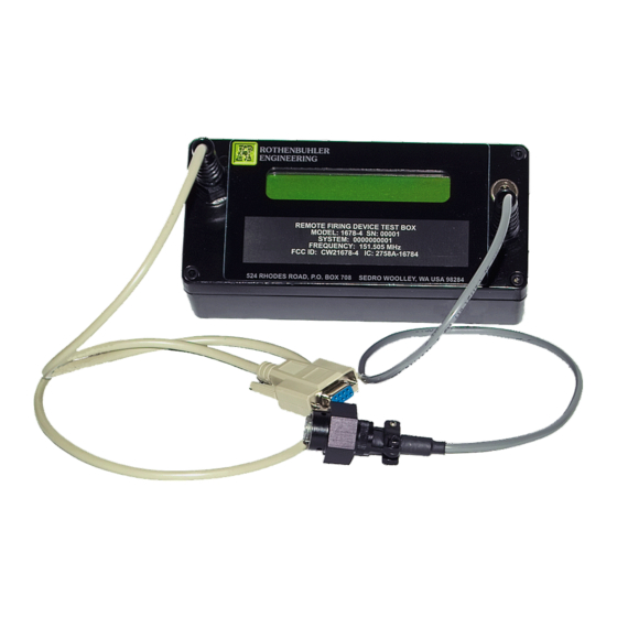
9. TEST BOX The Test Box allows the user to test display system information of the Electric Remote, RSTI, and Mini Controller Units as well as perform diagnostic checks. The Test Box also serves as the programming interface between a computer and a RFD Unit. Figure 9-1 Test Box 9.1. -
Page 65: Test Box Operation
9.1.3. Serial Connection: A serial cable connects the Test Box to a computer serial port operating at 1200 baud. The serial cable must be connected to a computer when the Test Box is being used to program Mini Controller and Remote Units. The serial cable may also be used when the Test Box is in the test mode. - Page 66 Next the Test Box will display the Battery Charge Count as shown below. This is the number of charge cycles the battery within the Mini Controller has experienced. Battery Charge Count Next the Test Box displays t he current battery’s temperature (+22C +72F) and chemistry type (NiMH).
- Page 67 The next message displayed is the Mini Controller’s serial number (S/N), unit Type (Model) date of manufacture (DOM), firmware version (Ver). S/N 00101 Type 1678-6 DOM 06/29/2010 Ve r 1.0 The next message displayed is the firmware Checksum and the Fire Count. Checksum 4C42 Fire Count 87 Next the Mini Controller begins a Battery Test.
- Page 68 Electric Remote Detected Next the Test Box will display the Battery Charge Count as shown below. This is the number of charge cycles the battery within the Electric Remote has experienced. Battery Charge Count Next the Test Box displays the current battery’s temperature (+22C +72F) and chemistry type (NiMH).
- Page 69 The next message displayed is the Electric Remote’s serial number (S/N), unit Type odel) date of manufacture (DOM) , firmware version (Ver). S/N 00101 Type 1678-6 DOM 06/29/2010 Ver 1.0 The next message displayed is the firmware Checksum and the Fire Count. Checksum 4C42 Fire Count 87 Next the Electric Remote begins the Electr...
- Page 70 Loaded Battery 7.24 <Low Battery = 7.00> fter testing is complete, the follow ing m ssage is displayed. Testing Completed 9.2.4. Testing the RSTI Do not touch the firing terminals of the Remote units while testing. A WARNING potentially lethal voltage is present during the Fire t est. To test an RSTI, install the firing tip on the top of the RSTI and plug the Test Box probe to the top connector on th e RSTI.
- Page 71 Battery SN 0001 Battery DOM 02/03/2011 The next message displayed shows the System Number or Address (0000000001) and the Unit that the RSTI is assigned to. Address 0000000001 Unit 3 The next message dis played shows the assigned Frequency and the Message Number. Frequency 174 MHz Message Number 010000 The next messages displayed are the serial number (S/N), unit Type (Mo...
- Page 72 Firing Voltage 2652 <Pass Level = 2250> Next the RSTI begins a Battery Test. Battery Test – Standby The Battery Test places a load on the battery and a countdown timer is started. At the end of the test, the loaded battery voltage is displayed along with the test limit of (7.00). Loaded Battery 7.24 <Low Battery = 7.00>...
-
Page 73: Saving Test Box Results To A File Using Hyperterminal
9.3. SAVING TEST BOX RESULTS TO A FILE USING HYPERTERMINAL A situation might occur where the end users want to be able to record the Test Box results, but they may not be authorized to use the ‘RFD Test Utility’ program because of its capability of reprogramming. - Page 74 Enter a name and choose an icon for the connection. Click the “OK” button. The dialog box shown below should appear. 1678 RFD OPERATION MANUAL {DRAFT}...
- Page 75 Click on the “Connect using:” list box and select either “Direct to Com1” or “Direct to Com2”. Select the one that corresponds with an unused serial port connector on the computer. Click the “OK” button. The dialog box shown below should appear. 1678 RFD OPERATION MANUAL {DRAFT}...
- Page 76 Click on the “Bits per second:” list box and select 1200. Leave the “Data bits:” set to ‘8’, “Parity:” set to ‘None’, “Stop bits:” set to ‘1’, and “Flow control:” set to ‘Hardware’ as shown in the following dialog box. 1678 RFD OPERATION MANUAL {DRAFT}...
- Page 77 Click the “OK” button. The dialog box shown below should appear. Click “Transfer” and then “Capture Text…”. The dialog box shown below should appear. Enter a file name for the text output from the Test Box and click the “Start” button. The dialog box shown below should appear.
- Page 78 Connect the Test Box serial cable to the serial port at the rear of the computer. This serial port must match up with the earlier selection of either “Direct to Com1” or “Direct to Com2”. Refer to documentation provided by computer manufacturer for more information on available serial ports.
- Page 79 Proceed with testing the 1678 system. The test results will be saved to a file. Select “File” and then “Print” to print the test results to the computer’s printer. Select “File” and then “Save” to save this onfiguration. For future tests on the same computer, start HyperTerminal, Select “F ile”...
-
Page 80: Rfd Programming Guide
10. RFD PROGRAMMING GUIDE 10.1. PROGRAMMABLE PARAMETERS 10.1.1. Mini Controller Unit • Operating frequency: Frequency is programmable, but if the new frequency is greater than 2MHz away from factory set frequency, the Mini Controller will have to be retuned at a factory authorized service center for optimum performance. - Page 81 • Run the setup.exe file from the folder. • Follow the prompts in the dialog boxes that app ear. Typical dialog boxes are shown below. 1678 RFD OPERATION MANUAL {DRAFT}...
-
Page 82: Configuring Setup Rfd
Setup 1669 RFD is now installed on the computer. 10.5. CONFIGURING SETUP RFD Follow the listed instructions to configure Setup RFD. • Click on the Windows “Start” button. • Go to “Programs” then “Setup RFD” and then click on “Setup RFD”. •... -
Page 83: Using Setup Rfd To Test Rfd Units
10.6. USING SETUP RFD TO TEST RFD UNITS The Setup RFD program may be used with the 166x Series Test Box to test 166x Series Units and record the results of those tests. 10.6.1. Creating a Test Results Log File: •... - Page 84 • If the file already exists, the following prompt appears. • Click “Y es” to append (add to) existing data or “No” to overwrite the existing file. • The following window appears. • A time and date stamp is added to the window. •...
- Page 85 • Connect the Test Box Probe to a Remote Unit. • Connect the Test Box Probe Leads to the Remote Unit binding posts. It does not matter which lead goes to which binding post. • The Test Box reads and displays the system information from the Remote Unit, and then executes an arm/fire test followed by a battery test.
- Page 86 • To test the Remote Unit again, remove the Test Box Probe from the Remote Unit for a few seconds, and then reconnect the Test Box Probe to the Remote Unit. • To end the testing and save the log file, click “File” and then “Close Log File…” 1678 RFD OPERATION MANUAL {DRAFT}...
- Page 87 10.6.2. Printing Test Results to a Log File • The log file must be printed from another Windows application such as Microsoft Word. • Start Word, click “File” and then “Open”. • Change the “Files of type:” list box to “All Files (*.*)” •...
-
Page 88: Using Setup Rfd To Program Rfd Units
10.7. USING SETUP RFD TO PROGRAM R FD UNITS Follow the listed instructions to use Setup RFD to Program RFD Units. • Click on the Windows “Start” button. • Go to “P rograms” then “Setup RFD” and then click on “Setup RFD”. •... - Page 89 • Connect the Test Box Probe to the Unit to be programmed. • The box labeled ‘Status’ updates automatically showing the type of unit connected. 1669-1 and 1669-21 designate Mini Controllers, 1669-2 and 1669-20 designate Remotes, 1669-14 and 1669-19 designate RSTIs. 1678 RFD OPERATION MANUAL {DRAFT}...
- Page 90 • With ‘Polling’ checked, the program will automatically read and display the unit’s current settings. • The “System Address” box displays the system address for the Unit. This number is unique to each system. • The “Unit Number” box displays the number for the Unit within the system. Remotes will be 1 through 8 and the Mini Controller will be Unit 0.
- Page 91 10.7.1. Changing the System Address The System Address is p rogrammable only on Remote and RSTI Units. It may not be changed on Mini Controller Units. The System Address should only be changed by personnel having that authority. A possible scenario for changing the System Address is that a Remote Unit in system 12345 has become unserviceable.
- Page 92 • Click on the “Frequency (MHz)” box and then type the desired Frequency in Mega Hertz in the box for both the transmit (TX) and receive (RX) boxes. Allowable entries are in the range of 150 to 174 Mega Hertz. CAUTION Changes to the TX operating frequency by more than 2 MHz on either side of the original frequency require retuning and must be performed by an authorized...
-
Page 93: Battery Maintenance
11. BATTERY MAINTENANCE The battery packs will provide optimum performance and maximum life when the following recommendations are adhered to. 11.1. BATTERY TEMPERATURE For maximum efficiency charge batteries when they are between 10 and 30 degrees Celsius. DO NOT attempt to CHARGE BATTERIES that are BELOW 0 degrees or ABOVE 40 degrees Celsius. - Page 94 Revision History: 1678 RFD OPERATION MANUAL {DRAFT}...
Need help?
Do you have a question about the 1678 REMOTE FIRING DEVICE and is the answer not in the manual?
Questions and answers