
Related Manuals for Sri PXS-710D

Summary of Contents for Sri PXS-710D
- Page 1 PXS-710D Podiatry X-Ray Source (Bi-Directional Operation) Installation/Operation Manual (Revision 0, S/N 501 …) Source-Ray, Inc. 50 Fleetwood Ct., Ronkonkoma, NY 11779 631-244-8200, 631- 244-7464 (Fax)
- Page 2 REVISION CONTROL Initiated Approved Rev Description Date Date Initial Release Steven L. 11/15/18 R. Manez 11/16/18...
-
Page 3: Table Of Contents
PXS-710D TABLE OF CONTENTS SECTION PAGE GENERAL INFORMATION Introduction Description Important Notice Responsibilities Electromagnetic Compatibility Warnings & Declarations Compliance Notice Safety Standards Electrical Specifications X-ray Tube Characteristics 1.10 X-ray Collimator 1.11 Mechanical Specification 1.12 Equipment Classification INSTALLATION AND CALIBRATION Un-Packaging... - Page 4 PXS-710D TABLE OF CONTENTS IGURES FIGURE DESCRIPTION PAGE Tube Characteristics X-Ray Tube Ratings Chart X-ray Tube Anode Cooling Chart X-ray Head Heating Chart X-ray Head Cooling Chart Collimator Front View Collimator Side View Focal Spot Location Source Dimensions 1.10 Zone Of Occupancy...
-
Page 5: List Of
PXS-710D TABLE OF CONTENTS ABLES TABLE DESCRIPTION PAGE Emissions & Immunity Chart mAs Increments Chart Technique Chart Approved 3 Party Control Software RS-232 Pin Out Generator OpalRad Communications Maintenance Checklist (Every 6 Months) Displayed Fault Conditions CHEMATICS SCHEMATIC DESCRIPTION PAGE... - Page 6 PXS-710D TABLE OF CONTENTS YMBOLS SYMBOL DESCRIPTION Exposure Switch Type “B” Applied Part Protective Earth Caution Pinch Point, Keep Hands Clear Warning- Electric Shock Hazard, Keep Hands Clear Refer to Instruction Manual Operator’s Manual; Operating Instructions Prescription Use (Part 21 CFR 801 Subpart D)
- Page 7 PXS-710D TABLE OF CONTENTS ABELS LABEL “A” LABEL “B” LABEL “C” LABEL “D” LABEL “F” LABEL “E” LABEL “H” LABEL “G” LABEL “J” LABEL “I”...
- Page 8 PXS-710D TABLE OF CONTENTS LABEL “L” LABEL “K” ABEL OCATIONS C A “J” & “H” B located inside of base G “K” located “K” located inside of base inside of base ...
-
Page 9: General Information
Section IV discusses theory of operation and Section V contains maintenance procedures and recommended intervals. ESCRIPTION The PXS-710D Podiatry X-Ray source is designed and manufactured by Source- Ray, Inc. It provides a high quality radiographic capability in a small lightweight format. The source consists of the following major assemblies: ... - Page 10 The PXS-710D contains no user serviceable parts. Only qualified and authorized personal shall operate this source. In this context, qualified means those legally permitted to operate this equipment in the jurisdiction in which the equipment is being used, and authorized means those authorized by the authority controlling the use of the equipment.
-
Page 11: Responsibilities
PXS-710D Section 1 ONTINUED: The boom arm presents a pinch hazard. Keep hands clear when in use. ESPONSIBILITIES To operate X-ray equipment it is required by state/country that the operator will be trained personnel. The operator must be familiar with safety requirements for operating the X-ray generator. -
Page 12: Electromagnetic Compatibility Warnings & Declarations
1.5.1 INSTRUCTIONS FOR USE [ENVIRONMENTS] The PXS-710D is intended for use in a Professional Health Care Facility. The PXS-710D may cause radio interference or may disrupt the operation of nearby equipment. It may be necessary to take mitigation measures, such as additional shielding or relocating or re-orienting the... - Page 13 1.5.1 ONTINUED: [ESSENTIAL PERFORMANCE] The ME Equipment, PXS-710D, shall be able to perform its Essential Performance and remain safe. The following degradation associated with Essential Performance shall not be allowed: Expose Loading Parameters KV, mA, Time and mAs set on the operator control panel (OCP) shall not be different than actual output of X-Ray generator KV, mA and mAs, Time.
- Page 14 (including peripherals such as antenna cables and external antennas) should be used no closer than 30 cm (12 inches) to any part of the PXS-710D, including cables specified by the manufacturer. Otherwise, degradation of the performance of this equipment could result.”...
- Page 15 PXS-710D Section 1 ABLE 1.1 MISSIONS & MMUNITY HART Emissions and Immunity Test Standards Compliance Immunity Test Level Emissions test Compliance (Professional Health Care Facility) Conducted Emissions Group 1, Class A Frequency Limit [dBuV] Range RF emissions Group 1 Quasi Peak...
- Page 16 PXS-710D Section 1 7% for equipment which is; Attended whilst in use (for example: hair dryers, vacuum cleaners, kitchen equipment such as mixers, garden equipment such as lawn mowers, portable tools such as electric drills), or Switched on automatically, or is intended to be switched on...
-
Page 17: Compliance Notice
X-Ray Generator/ Tube Housing (PXS-710D-G) Base Assembly Remote Control Module (Optional) INDICATION FOR USE: The model PXS-710D Podiatry X-Ray source is intended for General Purpose Radiographic exams utilizing film, computed radiography, or direct digital flat panels. Not for mammographic use. -
Page 18: Electrical Specifications
PXS-710D Section 1 LECTRICAL PECIFICATIONS MILLIAMPERES Milliamperes will not deviate from the selected value by more than + 5% within the operating line voltage range and within the specified range of line voltage regulation. KILOVOLTS Kilovoltage will not deviate from the selected value by more than + 5% of full scale MAS will not deviate from the selected value more than + 8% or 0.2 mAs... - Page 19 PXS-710D Section 1 ONTINUED: NOMINAL ELECTRIC POWER 700 W, Constant potential derived from a high frequency inverter source, Regulated for both kVp and mA. MAX OUTPUT POWER Instantaneous: 700W (70kV @ 10 mA) DUTY CYCLE (AUTOMATIC) 3.3% (ie.. X-ray Exposure 1 second ON, 30 seconds OFF) MINIMUM PERMANENT FILTRATION 1.8 mm of aluminum equivalent at 70 kVp...
-
Page 20: X-Ray Tube Characteristics
PXS-710D Section 1 ONTINUED: ENVIRONMENTAL OPERATING: Temperature: 40°F - 90°F (5°C - 32°C) Pressure: 70 kPa – 106 kPa Humidity: 30% - 90% (Non-Condensing) STORAGE: Temperature: 30°F - 110°F (-1°C - 43°C) Pressure: 70 kPa – 106 kPa ... - Page 21 PXS-710D Section 1 ONTINUED: INHERENT FILTRATION Minimum 0.65 mm aluminum equivalent at 80 kVp COOLING Natural convection through the insulating medium to the enclosure INSULATING MEDIUM Highly refined transformer oil; breakdown dielectric strength of not less than 45 kVp per ASTM...
-
Page 22: Tube Characteristics
PXS-710D Section 1 ONTINUED: THERMAL Oil insulation ANODE HEAT STORAGE 25,000 Heat Units ANODE COOLING RATE 200 Heat Units / sec. NOTE: Heat Unit = kVp x mAs IGURE 1.1 -RAY HARACTERISTICS... -
Page 23: X-Ray Tube Ratings Chart
PXS-710D Section 1 IGURE 1.2 -RAY ATING HARTS... -
Page 24: X-Ray Tube Anode Cooling Chart
PXS-710D Section 1 IGURE 1.3 Heating Curve (Generator Head) 55.0 50.0 45.0 40.0 35.0 30.0 25.0 20.0 90 120 150 180 210 240 270 MInutes IGURE 1.4 Cooling Curve (Generator Head) 60.00 50.00 40.00 30.00 20.00 10.00 0.00 30 60 90 120 150 180 210 240 270 300 330 Minutes IGURE 1.5... -
Page 25: X-Ray Collimator
PXS-710D Section 1 1.10 -RAY OLLIMATOR: Model: Collimare R72S Rating: 80 kVp LED Crosshairs (Center locator) Light Field (LED, 12VDC @ 2A, 24VDC @ 1A or 24VAC @ 1A) COMPLIES WITH DHHS RADIATION STANDARD 21 CFR SUBCHAPTER J Conforms to ANSI/AAMI ES60601-1 Certified to CSA STD C22.2 No.60601-1... -
Page 26: Collimator Front View
PXS-710D Section 1 IGURE 1.6 OLLIMATOR RONT IGURE 1.7 OLLIMATOR... -
Page 27: Equipment Classification
PXS-710D Section 1 1.12 QUIPMENT LASSIFICATION: Protection against electric shock: Class I with no applied parts. Protection against ingress of fluids: No protection against ingress of fluids (IPXO). Not suitable for use in oxygen rich environment. Mode of Operation: Non-continuous operation. -
Page 28: Source Dimensions
PXS-710D Section 1 IGURE 1.9 OURCE IMENSIONS... -
Page 29: Zone Of Occupancy
PXS-710D Section 1 SEE SECTION 1.3 OPERATOR ZONE OF OCCUPANCY (WHEN AT -90°) (WHEN AT 90°) SEE SECTION 1.3 SEE SECTION 1.3 IGURE 1.10 ONE OF CCUPANCY... -
Page 30: Installation And Calibration
PXS-710D Section 2 INSTALLATION AND CALIBRATION CAUTION This Section Pertains To Authorized Source-Ray Service Personnel Only The Podiatry Support Base contains a spring-loaded arm with 500 pounds of force. Never move the arm without the X-Ray head attached. Never remove the X-ray Head while the arm is in a position other than 90° (Vertical) Equipment installation and servicing procedures should be performed by properly trained and qualified service personal only. - Page 31 4) Lift the Arm (C) up 90° and remove the Patient Back Handrail (D) and put aside. 5) Remove the Patient Side Handrails (E) from the cushions and put aside. 6) Remove the back handrail cushion from the box. 7) Remove the Podiatry Source (Model PXS-710D) from the box and put aside.
-
Page 32: Assembly
PXS-710D Section 2 SSEMBLY (REFERENCE FIGURE 2.1 & 2.2) 1) Secure the Patient Side Handrails (A) to the left and right side of the Podiatry Base (B) from the outside using 4 ea. 1/4-20 x 2” SHCS (E). Tighten securely. -
Page 33: Handrail Assembly
PXS-710D Section 2 IGURE 2.2 ANDRAIL SSEMBLY... -
Page 34: Electrical Connections
PXS-710D Section 2 CAUTION Be certain that the primary power source (wall outlet) is the same rating as the voltage specified on the label, located on the rear panel of the x-ray control. The power cord acts as mains disconnect device. -
Page 35: Calibration Set-Up
PXS-710D Section 2 ALIBRATION ET-UP Connect the mAs meter to the phone jack (J3) located on the top back plate of the Control/Generator Assy. Place the kVp meter (Unfors model 514L) in the X-Ray field @ 30” SID, and run calibration procedure. - Page 36 PXS-710D Section 2 2.5.3 ONTINUED: There are eight Calibration adjustments: 40kVp Preheat, kVp 50kVp Preheat, kVp 60kVp Preheat, kVp 70kVp Preheat, kVp The displays will then change to; kVp: “04”, mAs: “0 – 255”, indicating that the source is ready to calibrate the 40kVp Preheat setting.
- Page 37 PXS-710D Section 2 2.5.3 ONTINUED: To increase or decrease the kVp, Press kV up or down. Each activation of the button increases or decreases the kVp approximately 05. kVp. The number displayed in the mAs window represents a digital code for kVp reference and is increased or decreased by one with each activation of the kV switches.
-
Page 38: View Menu
Section 2 2.5.4 ALIBRATION ODE (W/PXS-710D CALIBRATION UTILITY) The PXS-710D Calibration Utility allows calibration of the PXS-710D with a host computer connected to the Serial RS-232 Port of the Generator. The PXS-710D Calibration Utility CD-ROM is provided with this documentation. -
Page 39: Password Dialog Box
PXS-710D Section 2 2.5.4 ONTINUED: igure 2.4 assword ialog igure 2.5 alibration d. Select ‘‘Re-Calibrate XRay Controller’’ from the Calibration Menu. Click ‘Run’ to enter the Calibration wizard. Ref Fig. 2.5 e. The Calibration Displays the Current Calibration point, kVp, mA and... -
Page 40: Calibration Wizard
PXS-710D Section 2 2.5.4 ONTINUED: igure 2.6 alibration izard f. Make an exposure and measure the actual mA waveform on the Oscilloscope. g. To increase or decrease the Preheat, use the ‘Filament Preheat adjust’ slider to adjust Preheat up or down. The number displayed in the Preheat Raw window represents a digital code for Preheat reference and is increased or decreased by the slider control. -
Page 41: Settings Confirmation
PXS-710D Section 2 2.5.4 ONTINUED: j. Make an Exposure and verify the actual kVp value, Repeat step i if more adjustment is required. k. Using the attached mAs meter, measure the mAs for the 1 sec. exposure. Verify that the reading is 10.0 mAs (1.0 mAs +/- 5%). If adjustment is required, adjust R102 on the Control board assembly P/N 950132. -
Page 42: Settings Saved Confirmation
PXS-710D Section 2 2.5.4 ONTINUED: n. Once the new calibration settings are saved, a confirmation dialog is displayed. Click on ‘OK’ to proceed, you will be returned back to the “Calibration Menu”. Ref fig 2.8 igure 2.8 ettings aved onfirmation o. -
Page 43: Calibration Mode Selection
Section 2 2.5.5 NORMAL OPERATION (W/PXS-710D CALIBRATION UTILITY) The PXS-710D Calibration Utility can be used as a standalone controller for the PXS-710D allowing setting kVp, mAs and manual Exposure control. a. Start the PXS710D Utility, PXS710DCal.exe located in the following directory: C:\Program Files\PXS-710D\ b. -
Page 44: Calibration Mode Utility
PXS-710D Section 2 2.5.5 ONTINUED: igure 2.11 alibration TILITY d. kVp adjustment is accomplished by the UP and DOWN buttons located under the kVp display. e. Time/mAs adjustment is accomplished by the UP and DOWN buttons located under the Time Display. -
Page 45: Mas
PXS-710D Section 2 2.5.5 ONTINUED: g. To Make an X-Ray Exposure in the Cal Mode, press the EXPOSE button on the Exposure switch. Hold for the length of the exposure. Once the Exposure ends, release both the PREP and EXPOSE buttons on the Exposure switch. -
Page 46: Beam Alignment
PXS-710D Section 2 LIGNMENT Tighten yoke block to prevent movement during alignment. Rotate Collimator so that the knobs are facing front and tighten lock. Remove the collimator outer shroud by removing the 4 screws securing the shroud to the collimator. Place the phosphor screen in the beam at 30.6"... -
Page 47: Unit Operation
PXS-710D Section 3 UNIT OPERATION ONTROLS AND NDICATORS (CONTROL PANEL) DESCRIPTION FUNCTION 1) GENERATOR POWER SWITCH Power Switch Generator. Section 3.2 (Item H) for the Digital Imaging Panel Power Switch. 2) A.C. INPUT CONNECTOR Connects Control/Generator Assembly to supply mains. - Page 48 PXS-710D Section 3 ONTINUED: 12) X-RAY ON INDICATOR Color YELLOW 60601-1 Illuminates when exposure switch depressed to indicate that x-ray’s are being produced for the pre-set time interval. In addition, an audio tone is generated at the same time. 13) FAULT INDICATOR Color RED per 60601-1 3 Ed.
-
Page 49: Generator/Control Connector Description
PXS-710D Section 3 ONTINUED: igure 3.1 enerator/ ontrol onnector escriptions (Generator Bottom View) igure 3.2 ptional emote ontrol anel escriptions... -
Page 50: Control Panel Description
PXS-710D Section 3 ONTINUED: mAs Increments 0.20 0.45 1.00 2.20 5.00 11.00 25.00 56.00 125.00 0.22 0.50 1.10 2.50 5.60 12.50 28.00 63.00 140.00 0.25 0.56 1.25 2.80 6.30 14.00 32.00 71.00 160.00 0.28 0.63 1.40 3.20 7.10 16.00 36.00 80.00 ... -
Page 51: Source Base
PXS-710D Section 3 OURCE DESCRIPTION FUNCTION A. BOOM ARM Controls the angle adjustment of the Generator/Control Assembly. SHUTTER KNOBS Adjusts X-Ray field size. PATIENT SUPPORT RAIL Functions as a support point for patients. PATIENT BASE Functions as positioning area for patient. -
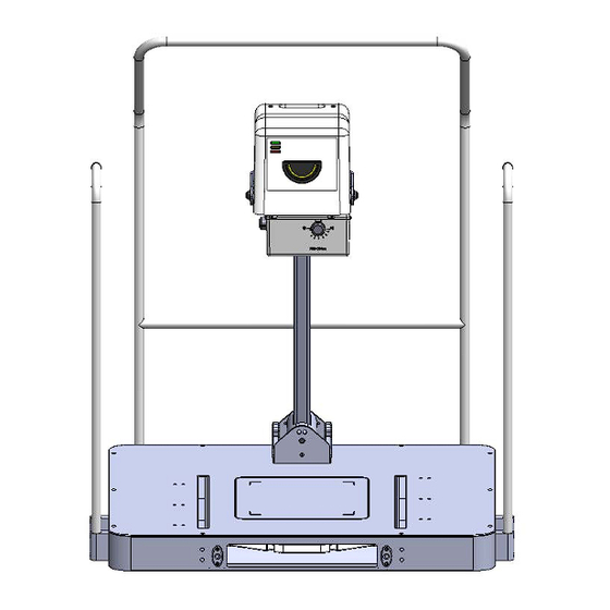
Page 52: Source Front View
PXS-710D Section 3 ONTINUED: igure 3.5 ource (Front View) -
Page 53: Source Side View (0° Head Tilt)
PXS-710D Section 3 ONTINUED: igure 3.6 ource (Side View, 0° Head Tilt) igure 3.7 ource (Side View, 15° Head Tilt) - Page 54 PXS-710D Section 3 ONTINUED: DESCRIPTION FUNCTION G. D.I.P. POWER SWITCH Power Switch for the Digital Imaging Panel (D.I.P.) Supply(s). See Section 3.1 (Item 1) for X-ray Source Power Switch. H. RS-232 CONNECTOR Pass-Thru connector for the RS-232 port for Generator control by a Host Application.
-
Page 55: Source Base (Rear Control Panel)
PXS-710D Section 3 ONTINUED: igure 3.8 ource ase (Rear Connector Panel) igure 3.9 ource ase (Side Connector Panel) -
Page 56: Operating Procedure (Generator/Control Assembly)
PXS-710D Section 3 PERATING ROCEDURES: (GENERATOR/CONTROL ASSEMBLY) CAUTION Do not attempt to connect or disconnect any interconnect cables without disconnecting the mains supply first. 3.3.1 ANUAL PERATION (OPTIONAL SR-115-RC) 1) Operate the “Power On” switch (1) to turn the primary power on. -
Page 57: Faults
All Faults may be Reset by Cycling AC Power to the Unit. For Item #2, The Optional Remote Control Provides a ‘RESET’ button. For Item #3, a Command may be sent from the Host to reset the PXS-710D. ... -
Page 58: Procedure
PXS-710D Section 3 PERATING ROCEDURE: (PODIATRY SUPPORT BASE) Move the Boom Arm (A) to the desired position and release, the Boom Arm will retain the current position. The Boom Arm position range Left to Right is from -90° to 90°. Front and back position range is -2° to +15°... - Page 59 PXS-710D Section 3 ABLE 3.2 ( ECHNIQUE HART XM3 PDR (Naomi): 400 speed. Examination Thickness Notes Foot Dorso-plantar (AP) Normal 55 -60 30” Lateral Normal 55 -60 36” Marked Lesion Normal 55 -60 30” Lateral Oblique Normal 55 -60 36”...
- Page 60 PXS-710D Section 3 HARRIS Axial projection of the heel is useful for demonstrating talo-calcaneal bars. Patient stands with both feet on the film. The patient leans forward slightly. The tube is positioned behind the patient and the central ray is angled 45 degrees towards the heels and is centered between the medial malleolus.
- Page 61 PXS-710D Section 3 CAUSTON METHOD Oblique foot projection to demonstrate the sesamoids. Position foot laterally, with the medial side against the cassette. Angle the central ray 40 degrees towards the ankle and center to the first metatarsophalangeal sesamoids.
-
Page 62: Theory Of Operation
(beam limiting device) assembly. The PXS-710D also can be controlled via a RS-232 Serial link, the RS-232 Serial link allows a 3 party computer application, OpalRad (Supplied by the End User), to communicate with the generator. - Page 63 PXS-710D Section 5 ONTINUED: The Power Board Inverter Assembly is powered by 115 VAC via connector TB1 (ref dwg. 100206). With circuit breaker CB1 closed, an AC voltage is applied through current limiting resistor R1 of the Power Board PWA. The voltage is then rectified and filtered via Diode Bridge D1 and Capacitors C1 –...
-
Page 64: Opalrad Generator Communications
3 Party Control Software The Serial hardware in the PXS-710D generator uses a 2.5KV Optically Isolated EIA/TIA-232E Compatible 3-wire interface. (Ref Figure 3.1 Item 6) This interface Operates at 19200 BAUD, 8N1. The Pin assignments are listed in Table 4.2... - Page 65 PXS-710D Section 5 ONTINUED: Pin # Function Description Signal Output Input Common able 4.2 S-232 The Serial Protocol used in this interface incorporates a data packet with a 16-bit CRC for error detection. Handshaking ACK and NAK replies are incorporated to enable error recovery.
- Page 66 PXS-710D Section 5 ONTINUED: The ERRORSTATUSCMD Request is used for retrieving the Generator Techniques and obtaining Error information. It is also used to verify the Generator is properly connected and powered ON. The OpalRad UAI will process any Errors returned and display them to the User.
- Page 67 PXS-710D Section 5 ONTINUED: If an Error Occurs or the User releases the PREP and/or XRAY switches the Exposure terminates. Otherwise the Exposure completes normally with the Techniques that were set. Once the Exposure is completed, a POSTGENCMD is sent to the Host.
-
Page 68: Unit Maintenance Page
PXS-710D Section 5 UNIT MAINTENANCE CAUTION This section pertains to authorized Source-Ray service personnel only Equipment installation and servicing procedures should be performed by properly trained and qualified service personal only. Protective covers are provided to shield service personal from inadvertent contact with high voltage components. -
Page 69: Ordering Information
AINTENANCE ROCEDURE Reference the checklist on following page. The PXS-710D contains no user serviceable parts. ARM- ROCEDURE If equipment has remained un-powered for an extended period of time, it will be necessary to bring the unit up slowly so that the high voltage circuits are not damaged. - Page 70 PXS-710D Section 5 ABLE 5.1 AINTENANCE HECKLIST (EVERY SIX MONTHS) MODEL: PXS-710D SERIAL # ___________ Beam Current (Reference Section 2.3) ____________ Tube Potential (Reference Section 2.4). ____________ Exposure time (Reference Section 2.5). ____________ Beam Alignment (Reference Section 2.6) ____________ Check voltage on X-Ray Generator at J2 pins A and B (collimator supply) with collimator unplugged (24 VDC).
- Page 71 LIMITED WARRANTY Source-Ray, Inc. warrants its Model PXS-710D Podiatry X-Ray Source to be free of manufacturing defects, which can impair their normal operation when used within their specified ratings. Claims under this warranty must be made within 3 years after shipment from the factory.
- Page 72 PXS-710D Section 5 CHEMATIC 5.1 IRING IAGRAM (100236_0)
- Page 73 PXS-710D Section 5 CHEMATIC 5.2 ENERATOR IRING IAGRAM (100206_1)
Need help?
Do you have a question about the PXS-710D and is the answer not in the manual?
Questions and answers