
Summary of Contents for Price Industries Limited FDC
- Page 1 MANUAL – INSTALLATION, OPERATION, & MAINTENANCE Fan Powered Constant Volume Terminals FDC, FDCLP2 v100 – Issue Date: 01/10/19 © 2019 Price Industries Limited. All rights reserved.
-
Page 2: Table Of Contents
Fan Powered Constant Volume terminals TABLE OF CONTENTS Installation Overview Quick Reference ............1 Receiving Inspection ............. 1 Caution to Contractors ..........1 Control Assembly Label ..........2 Installation & Mounting Instructions Mounting the Unit ............3 Duct Connection ............4 Control Connections ............. -
Page 3: Installation Overview
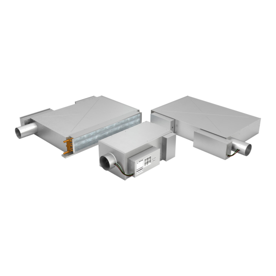
Fan Powered Constant Volume terminals InstallatIon overvIew Quick reference This manual applies to Price Series Fan Powered Terminal Unit models FDC, FDCLP2, and FDCLP2-DOAS. Air Flow Sensor The SP300 velocity sensor is normally supplied as standard with this terminal unit. -
Page 4: Receiving Inspection
Fan Powered Constant Volume terminals InstallatIon overvIew receiving inspection All Price fan powered terminal units are inspected before shipment. After unpacking the assembly, check it for damage. If any damage to the products is found, report it immediately to the delivery carrier. During unpacking and installation, do not handle the unit by the inlet velocity sensor. -
Page 5: Control Assembly Label
VAV SPECIFICATIONS VAV SPECIFICATIONS 957521 957521 Price Order No Price Order No FDCLP2 FDC-1-X Branch PO: Branch PO: Customer PO Customer PO PRICE RESEARCH CENTER PRICE RESEARCH CENTER Job Name: Job Name:... -
Page 6: Installation & Mounting Instructions
IS FIELD FLIPPABLE ON FDC TERMINAL UNITS. Rev Description ECN Date (y/m/d) By Print Date: 1/9/2019 - FDC Manual Image Rev A.dft Print Date: 1/9/2019 - FDC Manual Image Rev A.dft FAN POwERED CONSTANT VOLuME TERMINALS - Manual | priceindustries.com... -
Page 7: Duct Connection
Fan Powered Constant Volume terminals INSTALLATION & MOUNTING INSTRUCTIONS duct Connection Recommend a minimum of 3 duct diameters of straight inlet duct, either sheet metal or flexible, same size as the inlet, between the unit inlet and any transition, take-offs or fittings. Use of transitions or elbows at the unit inlet to be avoided. Where flexible duct is used it should be pulled tight to eliminate sags or folds. -
Page 8: Start Up & Operation
A fan powered terminal unit should never be operated if the downstream duct work has not been installed. A minimum downstream static pressure resistance of 0.1 in wg (or 0.2 in wg for Size 60 FDC units and units with an electric heater). -
Page 9: Electronically Commutated Motor (Ecm) Information
Fan Powered Constant Volume terminals start Up & operatIon electronically Commutated motor (eCm) information Do not switch 120/208/240/277 VAC power to turn ECM motor on and off. Instead control the 24VAC signal or BAS signal to turn the ECM motor on and off. The ECM motor has large capacitors that charge quickly on mains power up. Switching on several motors frequently could reduce building power quality and is not recommended. -
Page 10: Maintenance
Fan Powered Constant Volume terminals MaIntenance Fan and motor maintenance Disconnect all incoming power before servicing the unit. Price fan powered terminal units are supplied with permanently lubricated motors. The blower and motor should be inspected annually for accumulation of dust and dirt. Clean as necessary. To access blower and motor for servicing, remove the bottom access panel or alternate access panels if equipped. -
Page 11: Motor/Blower Field Replacement
Fan Powered Constant Volume terminals MaIntenance motor/Blower Field replacement Tools you will need to replace the motor/blower assembly in the field: • Cordless drill with a 1/4 inch nut driver bit. • 3/8 inch nut driver bit. • Wiring diagram (located inside the control panel). Recommended, but not required: •... - Page 12 Fan Powered Constant Volume terminals MaIntenance motor/Blower Field replacement Installation Instructions: Lift the blower assembly up and tilt into place. Start with the bottom two bolts first and tighten them by hand. Rotate the blower into position so the top two holes line up. Insert the bolts and hand-tighten them in place. Use the 3/8 inch nut driver to tighten them.
-
Page 13: Troubleshooting Guide
Measure the downstream static pressure. It needs to overheat and cycle. Ensure the downstream static be at least 0.1 in wg (0.2 in wg for a Size 60 FDC or pressure is a minimum of 0.1 in wg (0.2 in wg for a if an electric coil is present). -
Page 14: Replacement Parts
115V - 1/4 HP (FDC Size 20) 019 169-007 115V - 1/2 HP (FDC Size 30) 019 169-010 115V - 3/4 HP (FDC Size 40 & 60) 019 169-003 208-240V 1/8 HP (FDC Size 10) 019 169-006 208-240V - 1/4 HP (FDC Size 20) - Page 15 277/24V - 50VA Transformer 1” MERV 3 Filters Height Width 15.250 10.000 042297-074 FDC size 10 (with & without IAS) FDC size 20, 30, 40 (no IAS) and FDC size 20, 30, 17.875 15.875 042297-030 60 (with IAS, 2x required) 17.875 17.875 042297-031 FDC size 40 (with IAS) 19.875...
- Page 16 This document contains the most current product information as of this printing. For the most up-to-date product information, please go to priceindustries.com © 2019 Price Industries Limited. All rights reserved.
Need help?
Do you have a question about the FDC and is the answer not in the manual?
Questions and answers
What is the best way to do a fire alarm shut down on the box ?