Table of Contents
Advertisement
Advertisement
Table of Contents

Summary of Contents for Omicron CMGPS
- Page 1 Reference Manual CMGPS Synchronization Unit...
- Page 2 The user is responsible for every application that makes use of an OMICRON product. OMICRON electronics translates this manual from the source language English into a number of other languages. Any translation of this manual is done for local requirements, and in the event of a dispute...
-
Page 3: Table Of Contents
2.2 Purpose of the CMGPS ........ - Page 4 6.1 CMGPS in General ........
-
Page 5: Preface
Preface Preface The purpose of this reference manual is to familiarize users with the CMGPS synchronization unit and to show how to properly use it in various application areas. The reference manual contains important tips on how to use the CMGPS synchronization unit safely, properly, and efficiently. - Page 6 Principles, Designated Use • The CMGPS should only be used when in a technically sound condition. Its use should be in accordance with the safety regulations for the specific job site and application. Always be aware of the dangers of the high voltages and currents associated with this equipment.
- Page 7 Safe Operation Procedures • The CMGPS is to be set into operation in accordance with the information provided in section 4 ”Operating the CMGPS”. • The CMGPS must not be opened! If the device is opened, no guarantee claims can be made.
- Page 8 GPS Synchronization Unit CMGPS...
-
Page 9: Designated Use
Using the CMGPS for other purposes than those described above is not considered the designated use. The CMGPS's specifications have been determined in the course of a project to develop a mobile synchronization unit for CMC test sets. The CMGPS may not be installed stationary. - Page 10 GPS Synchronization Unit CMGPS...
-
Page 11: Introduction
Introduction 2 Introduction 2.1 What is GPS? The Global Positioning System (GPS) is one of two satellite navigation systems covering the whole earth. It was developed in 1978 by the US Department of Defence to replace TRANSIT, the first US satellite navigation system, and was initially designed to develop the defence ability of the USA. -
Page 12: Purpose Of The Cmgps
(see also section ”Technical Principles”). Based on this innovative test method by using two or more CMGPS extension units, two or more CMC test sets can be started simultaneously with a synchronization error of the CMGPS output of < 1 µs . -
Page 13: Construction And Functioning
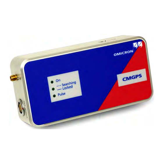
Construction and Functioning 3 Construction and Functioning 3.1 Components The CMGPS consists of the following components: Figure 3-1: Synchronization unit CMGPS Article number VEHZ3000 Figure 3-2: Power supply unit Article number VEHZ1103 100 - 240 V /18 V incl. plug-in adapter for... - Page 14 GPS Synchronization Unit CMGPS Figure 3-3: Article number VEHK0003 Connection cable ⇔ CMGPS ext. Interf. CMC test set Figure 3-4: Active antenna Article number VEHZ3001...
- Page 15 Article number VEHK3002 For cases that may require an extension of the antenna cable, an optional set of 2 × 20 m (2 x 60 ft) cables is available from OMICRON. Figure 3-6: 2 extension cables + SMA adapter (see also figure 3-7).
- Page 16 Figure 3-7: SMA adapter to connect Extension cables the extension cables to CMGPS and antenna Connect to antenna Connect to CMGPS • Protecting cap for antenna input (no illustration) • Carrying bag for CMGPS (no illustration) • User manual (no illustration)
-
Page 17: Led Status Display
1. This time may increase to up to 20 minutes in cases where the CMGPS was either relocated by several hundred kilometers since the last time it was in use or out of operation for more than... - Page 18 GPS Synchronization Unit CMGPS Synchronization pulse LED "ON" is lit. LED "Searching/Locked" is lit. Searching Locked LED "Pulse" is lit for approx. 500 ms during the Pulse output of the synchronization pulse at the outputs Pulse out 1 and/or Pulse out 2.
-
Page 19: Connections And Interfaces
Construction and Functioning 3.3 Connections and Interfaces 3.3.1 DC in Power Supply Power supply is applied to the CMGPS by means of a power supply unit 100-240 V /18 V , which is equipped with an adapter for the various country-specific wall outlets (see figure 3-2 on page 13). -
Page 20: Antenna Input
CMGPS Antenna input The antenna is connected to the antenna input of the CMGPS (SMA socket) by means of the RG58 coaxial extension cable (see figure 3-5 on page 15). This extension cable also serves as power supply cable for the antenna of the CMGPS. -
Page 21: Ext. Interf
Communication interface to connect CMGPS to the CMC test set’s ext. Interf. At this interface, the CMGPS is connected to the CMC test set by means of the supplied connection cable (see figure 3-3 on page 14). This interface serves to •... -
Page 22: Pulse Out 2 Interface
CMC's binary inputs (see also documentation of the test set and/or software). By means of the Pulse out 2 interface, the CMGPS can also be utilized as "standalone" synchronization unit without being connected to a CMC test set. -
Page 23: Block Diagram Of The Cmgps
Construction and Functioning 3.3.5 Block Diagram of the CMGPS Figure 3-12: 18 V from Block diagram of power supply unit the CMGPS DC input + 5 V DC/DC Antenna GPS receiver input ext. Interf. Pulse out 2 Interface modul Pulse... - Page 24 GPS Synchronization Unit CMGPS...
-
Page 25: Operating The Cmgps
Do not position the antenna of the CMGPS in an exposed position above the lightning rod or at another location endangered by lightning. In addition, do not position the antenna within a control cabinet in the vicinity of... -
Page 26: Connecting The Cmgps To A Cmc Test Set
The following explanations are based on successful initialization and on the fact that the CMGPS locked itself to the GPS signal. The state of the LEDs of the CMGPS should then be as follows: LED "ON" is lit. LED "Searching/Locked" is lit. -
Page 27: Connecting The Cmgps To A Cmc 56
4.2 Connecting the CMGPS to a CMC 56 Earlier versions of the CMC 56 test set do not have an ext. Interf. connector at their rear side. If you have such a test set, connect the CMGPS to a binary input instead. - Page 28 GPS Synchronization Unit CMGPS...
-
Page 29: Synchronizing Two Or More Cmc Test Sets
100 % of the protected line segment. Here, two CMGPS synchronization units trigger two CMC test sets to start a test at the exact same point of time. Since the GPS signal is available worldwide, the physical distance between these test sets is thereby of no relevance ("end to... -
Page 30: Standard Accuracy Mode
— performs this function. The two devices are synchronized by means of a CMGPS. After the CMGPS synchronization units have received signals from a sufficient number of satellites, they can determine the exact time. Figure 5-2: ±... -
Page 31: Enhanced Accuracy Mode
Note that the 5 µs accuracy is restricted to the test start only. It does not apply to actions triggered by the following GPS pulses 1. Error corresponds to amplifier output signals (voltage/current) of CMGPS-synchronized test sets at configured GPS trigger event. -
Page 32: Using Cmgps In Conjunction With Cmirig-B
IRIG-B time reference signal (DC level shift protocol B00x). That way, two or more CMC test sets are synchronized. Furthermore, an optional CMGPS synchronization unit can be integrated into the test setup to serve as source of the synchronization moment or 1PPS signal, respectively. - Page 33 Detailed information about how to configure the Test Universe software component Time Trigger Configuration for the use of CMIRIG-B with or without CMGPS can be found in the CMIRIG-B Reference Manual and in the Test Universe Help, topics Time Trigger Configuration and Hardware Configuration (IRIG-B & GPS tab).
- Page 34 GPS Syncronization Unit CMGPS...
-
Page 35: Technical Data
4 - 5 satellites to determine position and time — depending on the signal quality. 2. TTFF = Time span the CMGPS needs to receive a sufficient number of satellite signals after switching on (to be "locked" to the signals). The higher the synchronization accuracy set via μ... -
Page 36: Power Supply
1. There is an optional extension set of 2 x 20 m (2 x 60 ft.) with SMA adapters available for a total extension of 40 m (120 ft.); refer to Table 8-1: ”Ordering information for the CMGPS synchronization (set)” on page 43. -
Page 37: Ext. Interf
First synchronization point of Programmable time 1. Accuracy of CMGPS. The synchronization of test sets depends on the accuracy set in the Test Universe software. Also refer to chapters 5.1 ”Standard Accuracy Mode” and 5.2 ”Enhanced Accuracy Mode” ... -
Page 38: Pulse Out 2 Interface
30 V (red socket +, black socket –) CEmax 1. Depending on accuracy set in the Test Universe software The synchronization pulse is only put out if the CMGPS is able to meet the accuracy configured by the software. -
Page 39: Ce Conformity, Electromagnetic Compatibility
Technical Data 6.7 CE Conformity, Electromagnetic Compatibility Table 6-7: Electromagnetic CE Conformity Compatibility The product adheres to the specifications of the guidelines of the council of the European Community for meeting the requirements of the member states regarding the electromagnetic compatibility (EMC) Directive 2004/108/EC and the low voltage Directive 2006/95/EC. -
Page 40: Safety Standards, Certificates
GPS Synchronization Unit CMGPS 6.9 Safety Standards, Certificates Table 6-9: Safety Standards, Certified Safety Standards Certificates Europe EN 61010-1 Insulation of Pulse out 2 interface with regard to housing and/or ext. Interf. complies with EN 60950-1. International IEC 61010-1 UL 61010-1 Canada CAN/CSA-C22.2 No 61010-1-04... -
Page 41: Faults, Possible Causes, Remedies
7 Faults, Possible Causes, Remedies Table 7-1: Fault Possible cause Remedy Faults, possible causes and elimination - I CMGPS without power, Power supply unit Check output voltage of LED "ON" is off. defective. the power supply unit by means of a voltmeter... - Page 42 Remedy Faults, possible causes and elimination - IV LED "Searching/Locked" Timing parameter for Check the settings by is lit, CMGPS is locked putting out the means of the software. If to the GPS signal, but synchronization pulse is necessary change there is no set wrong or too long.
-
Page 43: Appendix
CMGPS CMGPS synchronization unit set, consisting of VEHZ3000 synchronization (set) – CMGPS synchronization unit (see figure 3-1 on page 13) – power supply unit 100 - 240 V /18 V , incl. plug-in adapter for various country-specific wall outlets –... -
Page 44: Cleaning
GPS Syncronization Unit CMGPS 8.2 Cleaning To clean the CMGPS, use a cloth dampened with isopropanol alcohol or water. Prior to cleaning, always unplug the CMGPS from the mains and disconnect CMGPS from the CMC test set. -
Page 45: Contact Information / Technical Support
6833 Klaus, Austria Phone: +43 5523 507-333 E-Mail: support@omicron.at Web: http://www.omicron.at For addresses of OMICRON offices with customer service centers, regional sales offices or offices for training, consulting and commissioning, please see the Contact section of our Web site http://www.omicron.at. - Page 46 Contact Information / Technical Support...
-
Page 47: Index
Designated use of CMGPS ....9 Dimensions of CMGPS ....35 address OMICRON addresses . - Page 48 IRIG-B time reference ....32 Web site OMICRON Web site ....45 Weight - technical specifications ..35 NAVSTAR satellites .
Need help?
Do you have a question about the CMGPS and is the answer not in the manual?
Questions and answers