
Summary of Contents for Power-Genex LSB-1000 Series
- Page 1 Instruction and Operating Manual Safe Area Limit Switch Box LSB-1000 Series Ver. 1.0...
-
Page 2: Table Of Contents
LSB-1000 Series Table of Content 1. Safety Instructions / Precautions 2. Overview of Structure. 3. Product Specifications / Features 4. Name Plate 5. Part Numbering System (order code) 6. Specifications of Switch and Sensors 6.1 Mechanical Switch 6.2 P&F Proximity Sensors NJ2-V3-N 7. -
Page 3: Safety Instructions / Precautions
3. Before machinery/equipment is restarted, take measures to prevent unexpected operation and malfunction. 4. Contact POWER-GENEX beforehand and take special consideration of safety measures if the product is to be used in any of the following conditions. 1. Conditions and environments outside of the given specifications, or use outdoors or in a place exposed to direct sunlight. - Page 4 Deterioration of rubber materials are not covered by the limited warranty. Compliance Requirements 1. The use of POWER-GENEX products with production equipment for the manufacture of weapons of mass destruction (WMD) or any other weapon is strictly prohibited. 2. The exports of POWER-GENEX products or technology from one country to another are governed by the relevant security laws and regulations of the countries involved in the transaction.
- Page 5 LSB-1000 Series 1-3. Precautions Operation Warning 1. Do not operate the Switch Box outside the specified range as this may cause problems. (Refer to the specifications.) 2. Design the system to include a safety circuit to avoid the risk of danger should the Switch Box suffer failure.
- Page 6 LSB-1000 Series 1-4. Precautions Handling Caution 1. Avoid excessive vibration or impact to the Switch Box body and any excessive force to the armature, as these actions may cause damage to the product. Handle carefully while transporting and operating. 2. If being used in a place where vibration occurs, using a binding band is recommended to prevent broken wires because of the vibration.
-
Page 7: Overview Of Structure
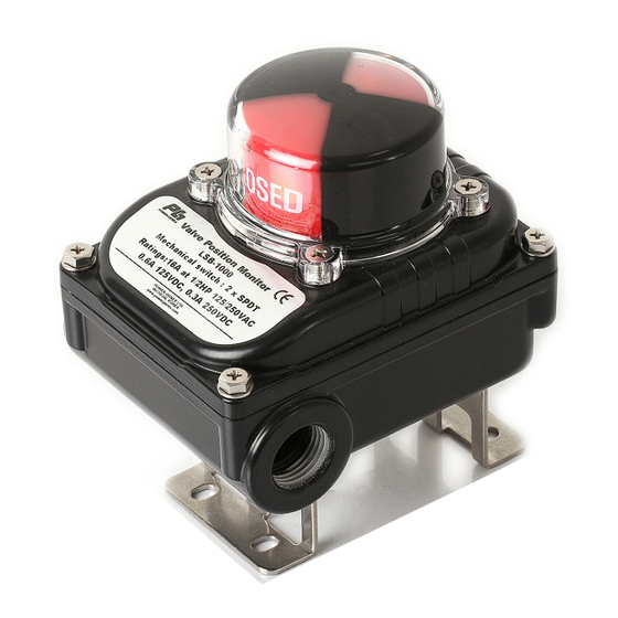
LSB-1000 Series 2. Overview of Structure This product is composed with following parts • SPDT Mechanical / P&F Proximity Sensor NJ2-V3-N / Autonics Proximity SensorPSN17-D / Honeywell SPDT limit Switches • NAMUR Mounting Shaft and Brackets Below are descriptions and the internal view of the product with open cover. -
Page 8: Nameplate
LSB-1000 Series 3. Product Specifications Product LSB-1000 Protection Rate Waterproof Dustproof IP67 (Option IP68) Mechanical Switch (2) SPDT, (4) SPDT P&F Proximity Sensor (2)NJ2-V3-N Switch / Sensor Autonics Proximity Sensor (2)PSN17-5D Honeywell Mechanical Switch (2)SPDT Hermetically-sealed magnetic Sensor (2)MS-20 Operating Temperature -40 ~ +100℃... -
Page 9: Part Numbering System (Order Code)
LSB-1000 Series Part Numbering System (order code) LSB — 1 x — x Switch / Sensor 2 x SPDT Mechanical Switch 4 x SPDT 2 x NJ2-V3-N / P&F Proximity Sensor 2 x PSN17-5D (PNP or NPN) Autonics 2 x SPDT (Silver) -
Page 10: Specifications Of Switch And Sensors
LSB-1000 Series 6. Specifications of Switches and Sensors 6.1 Mechanical Switch 6.1.1 SPDT, SZM-V16-2FA-61 Non-Inductive Override Inductive override Model Resistance Lamp Inductivity Motor 250VAC 8VDC < SPDT Mechanical Switch> Allowed 30VDC voltage 125VDC 0.6A 0.1A 0.6A 0.1A 250VDC 0.3A 0.05A 0.3A... -
Page 11: Mechanical Switch
LSB-1000 Series 7. Wirings ① Supply voltage and current as mentioned in this manual. Otherwise, it may cause critical damages to the product or malfunctions. ② When using the product, earth the internal and external electrical box. ③ Check +, - Polarity correctly before connection. - Page 12 LSB-1000 Series 8. Adjusting Switch Cams a) Users can make change the default position of the Cam. b) Pull the Cam up as shown on the diagram to turn. c) Turn the Red Cam to a position where user wishes to operate limit switches and push the Cam down to adjust.
-
Page 13: Dimensions
LSB-1000 Series 9. Dimensions Bracket Size jjautomation.com... - Page 14 LSB-1000 Series J+J Automation UK Ltd Units 5 & 6 Lime Tree Business Park Matlock Derbyshire DE4 3EJ U.K. : +44-1629-55577 Home Page http://www.powergenex.com Subject to change without prior notice jjautomation.com...
Need help?
Do you have a question about the LSB-1000 Series and is the answer not in the manual?
Questions and answers