Table of Contents
Advertisement
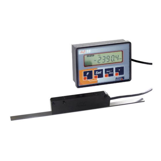
E series
Installation manual
Battery powered Absolute Linear Encoder System
Complete with an Indicator and an external Magnet Sensor with 0.1 mm resolution
Features
• Measuring distances up to 8 meters possible
• Unique definition of the zero point
(no further referencing necessary)
• Permanent retention of all data and settings
• Reserve energy up to 3 years
• AUTO-POWER-OFF function with adjustable „switch on" time
• Switch over for absolute / incremental mode
• Millimeters or Inches operation
• Fraction views in the Inch mode possible
• User friendly menu levels
• Keys can be enabled or disabled individually
• Adjustable reference value and 3 tool offsets
• Symbols individually selectable (mm/inches/arrows etc.)
AZ16E-000-E_10-06.doc
Doku Art. Nr. 799000026
Advertisement
Table of Contents

Related Manuals for ELGO Electric AZ16E Series

Summary of Contents for ELGO Electric AZ16E Series
- Page 1 E series Installation manual Battery powered Absolute Linear Encoder System Complete with an Indicator and an external Magnet Sensor with 0.1 mm resolution Features • Measuring distances up to 8 meters possible • Unique definition of the zero point (no further referencing necessary) •...
-
Page 2: Table Of Contents
1. INTRODUCTION 2. SAFETY 3. DETERMINATION OF THE RAIL AND TAPE LENGTH 4. DISPLAY ASSIGNMENT 5. THE AZ16E IN OPERATION 5.1 Initial operation 5.1.1 Detection of measuring direction 5.1.2 Referencing 5.3 Parameter settings 5.4 Parameter list 6. BATTERY CHANGE 7. MAGNETIC TAPE 7.1 Handling 7.2 Processing note for sticking 7.3 Resistance to chemicals of the magnetic tape... -
Page 3: Introduction
Attention! The company ELGO Electric GmbH is not liable for possible damages to machines and or to persons, which can result from defective material at the measuring sys- tem and the following circuit. The machine manufacturer is responsible for taking... -
Page 4: Determination Of The Rail And Tape Length
3. Determination of the rail and tape length Basically the following applies with an order of magnetic tape: Ordered length of tape = effective measuring distance + 100 mm For further details see the „Type designation“ at the end of the manual. 4. - Page 5 5.2 Basic functions (overview) Switch back from the sleep mode The unit switches into the sleep mode after completion of the adjustable time in register P04, if there are no changes in the display value and no key is pressed. To switch back from the sleep mode, the button F must be pressed.
-
Page 6: Parameter Settings
5.3 Parameter settings 1) Press button F for 3 seconds. "P01" (Parameter 01) appears in the display window. 3 sec. 2) Press button F The appropriate parameter value appears in the display 3) Select the desired decade by pressing Set 4) Adjust the desired value by using the Incr/Abs button Incr/ 5) Press F to select the next parameter... -
Page 7: Parameter List
5.4 Parameter list P 01 / Configuration of system: ( default setting = 11100 ) X X X X X Positive counting direction Negative counting direction mm operation (0.1 mm resolution) Inch operation (0.1 inches resolution) mm/Inch symbol disabled mm/Inch symbol enabled Arrow symbol for „positive direction“... -
Page 8: Battery Change
Parameter list (continuation) P 08 / Position scaling factor: ( default setting = 1.000 ) 0.001 ... 9.999 (the position value is multiplied by the factor adjusted here) P 09 / Reference value: ( default setting = 0.0 mm / 0.000 Inch ) - 999999.9 mm ... -
Page 9: Magnetic Tape
7. Magnetic Tape The magnetic tape consists of 3 components (see picture 1) a magnetized flexible rubber tape (Pos. 3), which is connected factory made with a • steel band (Pos. 5) and a • covering band (Pos. 1) , which is intended for the protection of the rubber tape. •... -
Page 10: Processing Note For Sticking
7.2 Processing note for sticking The provided sticky tapes stick well on clean, dry and plain surfaces. The more pollution exists the more proper the surface has to be. A surface roughness of R <= 3,2 (R <= 25 / N8) is rec- ommendable. -
Page 11: Technical Specifications
8. Technical specifications AZ16E (battery powered absolute encoder and indicator system with an external sensor) POWER SUPPLY 1 commercial battery size C (1.5 V) Battery service life 1... 3 years (depends on adjusted switch-on time) Distance Sensor - Tape max. 1.5 mm Resolution of encoder 0.1 mm Measuring units mm’s or INCHES Measuring length max. -
Page 12: Dimensions
9. Dimensions 9.1 Display Unit: * minus 9 mm, plug can be bended 34 * 37 (Install depth) Panel c ut out: B x H = 93 x 67 mm... -
Page 13: External Magnet Sensor „Azs
9.2 External Magnet Sensor „AZS“: Ø 6 Ø 3.4 10. Installation / Display Unit For mounting into a panel serves 2 small mount- ing plates with grub screws (included in the deliv- ery, see image right). The unit must be pushed from the front into the cut-out and fixed from the rear by the grub screws at the instrument panel then. -
Page 14: Type Designation
11. Type designation AZ16E- 000- 03.0- Type AZ16E: Indicator with external sensor SN- Number 000 = standard 001 = first special version etc. Power supply (1.5 V) 1 = one internal size C battery (standard) 2 = two internal size AA batteries 3 = external battery case Sensor cable lenght (max. -
Page 15: Liability Exclusion / Guarantee
The guarantee period is one calendar years from the date of delivery and includes the delivered unit with all its components. ELGO Electric GmbH will at its option replace or repair without charge de- fects at the unit or the included parts, verifiable caused by faulty manufacturing and/or material in spite of proper handling and compliance to the instruction manual.
Need help?
Do you have a question about the AZ16E Series and is the answer not in the manual?
Questions and answers