
Subscribe to Our Youtube Channel
Summary of Contents for Homematic IP HmIPW-DRI32
- Page 1 Installations- und Bedienungsanleitung Installation instruction and operating manual Wired Eingangsmodul – 32-fach S. 2 Wired Input Module – 32 channels p. 31 HmIPW-DRI32...
- Page 2 Lieferumfang Anzahl Bezeichnung Homematic IP Wired Eingangsmodul – 32-fach Bus-Verbindungskabel Bus-Blindstopfen Bedienungsanleitung Dokumentation © 2018 eQ-3 AG, Deutschland Alle Rechte vorbehalten. Ohne schriftliche Zustimmung des Herausgebers darf diese Anleitung auch nicht auszugsweise in irgendeiner Form reproduziert werden oder unter Verwendung elektronischer, mechanischer oder chemischer Verfahren verviel- fältigt oder verarbeitet werden.
- Page 3 °C...
-
Page 7: Table Of Contents
Montage und Installation ...........18 Anlernen ................20 5.4.1 Anlernen an die Zentrale CCU3 ......21 5.4.2 Anlernen an die Homematic IP Cloud per Wired Access Point ..........23 Bedienung ................25 Fehlercodes und Blinkfolgen ........27 Wiederherstellung der Werkseinstellungen ....28 Wartung und Reinigung ..........29... -
Page 8: Hinweise Zur Anleitung
Hinweise zur Anleitung Hinweise zur Anleitung Lesen Sie diese Anleitung sorgfältig, bevor Sie Ihr Home- matic IP Wired Gerät in Betrieb nehmen. Bewahren Sie die Anleitung zum späteren Nachschlagen auf! Wenn Sie das Gerät anderen Personen zur Nutzung über- lassen, übergeben Sie auch diese Anleitung. Benutzte Symbole: Achtung! Hier wird auf eine Gefahr hingewiesen. - Page 9 Gefahrenhinweise Verwenden Sie das Gerät nicht, wenn es von au- ßen erkennbare Schäden, z. B. am Gehäuse, an Bedienelementen oder an den Anschlussbuchsen ausweist. Lassen Sie das Gerät im Zweifelsfall von einer Fachkraft prüfen. Betreiben Sie das Gerät nur in trockener sowie staubfreier Umgebung, setzen Sie es keinem Ein- fluss von Feuchtigkeit, Vibrationen, ständiger Sonnen- oder anderer Wärmeeinstrahlung, Kälte...
- Page 10 Bei der Planung und Errichtung sind die ein- schlägigen Normen und Richtlinien des Landes zu beachten. Das Eingangsmodul ist ausschließ- lich für den Betrieb am Homematic IP Wired Bus vorgesehen. Der Homematic IP Wired Bus ist ein SELV-Stromkreis. Die Netzspannung der Ge- bäudeinstallation und der Homematic IP Wired...
- Page 11 Gefahrenhinweise Beachten Sie beim Anschluss an die Geräteklem- men die hierfür zulässigen Leitungen und Lei- tungsquerschnitte. Vor Einbau und Anschluss des Gerätes freischal- ten und spannungsführende Teile in der Umge- bung abdecken. Das Gerät ist nur für den Einsatz in Wohnberei- chen, Geschäfts- und Gewerbebereichen sowie in Kleinbetrieben bestimmt.
-
Page 12: Funktion Und Geräteübersicht
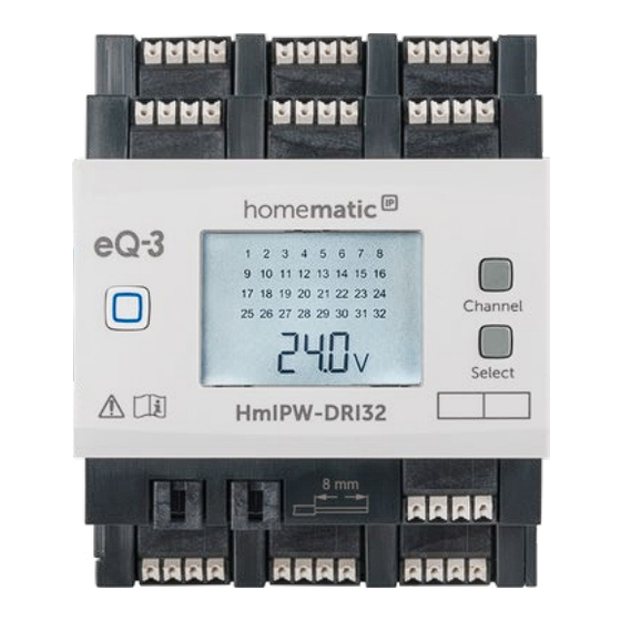
Funktion und Geräteübersicht Funktion und Geräteübersicht Das Homematic IP Wired Eingangsmodul – 32-fach lässt sich einfach auf einer Hutschiene in einem Stromkreis- verteiler montieren. Über 32 Eingänge können mehrere Schalter und Taster angeschlossen werden. Dies ermög- licht das Schalten oder Dimmen von Lampen oder ande- ren Beleuchtungsanlagen über angelernte Homematic IP... - Page 13 Funktion und Geräteübersicht °C Geräteübersicht (s. Abbildung 1): Systemtaste (Anlerntaste und LED) Channel-Taste °C Select-Taste LC-Display Busanschluss 1 Busanschluss 2 Eingangs klemmen Masseklemmen (GND) Displayübersicht (s. Abbildung 1): Symbol Bedeutung Eingang nicht betätigt Eingang betätigt Daten werden vom Bus empfangen Daten werden zum Bus gesendet Temperaturangabe (eingeschaltet, wenn Temperatur angezeigt wird)
-
Page 14: Allgemeine Systeminformationen
Allgemeine Systeminformationen Allgemeine Systeminformationen Dieses Gerät ist Teil des Homematic IP Smart-Home- Systems und kommuniziert über das Homematic IP Pro- tokoll. Sie haben die Möglichkeit, alle Geräte des Systems komfortabel und individuell über die Bedienoberfläche der Zentrale CCU3 oder flexibel per Smartphone über die Homematic IP App in Verbindung mit der Homema-... - Page 15 Inbetriebnahme Aus Gründen der elektrischen Sicherheit darf zum Anschluss des Homematic IP Wired Bus aus- schließlich das mitgelieferte Homematic IP Wired Buskabel oder ein als Zubehör erhältliches eQ-3 Homematic IP Wired Buskabel anderer Länge verwendet werden. Starre Leiter können zum Anschließen direkt in die Klemmstelle gesteckt werden (Push-In-Technik).
- Page 16 Inbetriebnahme • das Leben der Nutzer der elektrischen Anlage. Mit einer unsachgemäßen Installation riskieren Sie schwere Sachschäden, z. B. durch Brand. Es droht für Sie die persönliche Haftung bei Personen- und Sachschäden. Wenden Sie sich an einen Elektroinstallateur! Erforderliche Fachkenntnisse für die Installation: Für die Installation sind insbesondere folgende Fachkenntnisse er- forderlich: •...
-
Page 17: Auswahl Der Spannungsversorgung
0,25-1,50 Auswahl der Spannungsversorgung Die Spannungsversorgung des Eingangsmoduls erfolgt ausschließlich über den Homematic IP Wired Bus. Der Bus wird vom Homematic IP Wired Access Point (HmIPW- DRAP) gespeist (s. Bedienungsanleitung vom HmIPW- DRAP). Die maximale Gesamtstromaufnahme berechnet sich aus der Anzahl der tatsächlich verwendeten Eingänge. Durch jeden betätigten Eingang fließen ca. -
Page 18: Montage Und Installation
Sie mit der Installation beginnen. Bevor Sie das Gerät installieren und in Betrieb nehmen können, müssen Sie zunächst einen Homematic IP Wired Access Point (HmIPW- DRAP) in Betrieb nehmen. Bitte notieren Sie sich vor der Installation die auf dem Gerät angebrachte Gerätenummer (SGTIN) und den Verwendungszweck, damit Sie das Gerät... - Page 19 Inbetriebnahme cherheitsregeln). • Entfernen Sie die Abdeckung des Stromkreisver- teilers. • Setzen Sie das Eingangsmodul auf die Hutschiene auf (s. Abbildung 3). Achten Sie darauf, dass die Schrift auf dem Gerät und im Display für Sie lesbar ist und die Anschlussklemmen der Ka näle 1 bis 8 und 17 bis 28 oben liegen.
-
Page 20: Anlernen
Bitte lesen Sie diesen Abschnitt erst vollständig, bevor Sie mit dem Anlernen beginnen. Richten Sie zunächst Ihren Homematic IP Wired Access Point ein, um weitere Homematic IP Wi- red Geräte im System nutzen zu können. Aus- führliche Informationen dazu finden Sie in der Bedienungsanleitung des Wired Access Points. -
Page 21: Anlernen An Die Zentrale Ccu3
Um das Eingangsmodul an die Zentrale CCU3 anzulernen, gehen Sie wie folgt vor: • Richten Sie zunächst Ihre Zentrale CCU3 gemäß der zugehörigen Bedienungsanleitung ein und lernen Sie den Homematic IP Wired Access Point • Starten Sie die Benutzeroberfläche „Homematic WebUI“ auf Ihrem PC. •... - Page 22 Inbetriebnahme • Nach dem Anschluss an die Busleitung, ist der Anlernmodus des Eingangsmoduls für 3 Minuten aktiv. Sind die 3 Minuten noch nicht verstrichen, wird das Gerät automatisch angelernt. Sie können den Anlernmodus manuell für weitere 3 Minuten starten, indem Sie die Systemtaste (A) kurz drücken (s.
-
Page 23: Anlernen An Die Homematic Ip Cloud Per Wired Access Point
5.4.2 Anlernen an die Homematic IP Cloud per Wired Access Point Wenn Sie Ihre Homematic IP Wired Geräte flexibel per Smartphone-App steuern möchten, können Sie die Homematic IP Wired Geräte einfach an die Homematic IP Cloud anlernen. Gehen Sie dazu wie folgt vor: •... - Page 24 Inbetriebnahme Smartphone. • Lernen Sie den Homematic IP Wired Access Point gemäß der zugehörigen Bedienungsanleitung über die Smartphone-App an die Homematic IP Cloud an. Wählen Sie den Menüpunkt „Gerät anlernen“ aus. • • Nach dem Anschluss an die Busleitung, ist der An- lernmodus des Eingangsmoduls für 3 Minuten aktiv.
-
Page 25: Bedienung
• Vergeben Sie in der App einen Namen für das Ge- rät und ordnen Sie es einem Raum zu. Wenn Sie bereits Homematic IP Geräte im Smart- Home-System nutzen oder Ihre Wired Geräte mit Funk-Komponenten von Homematic IP kombi- nieren möchten, können Sie die Homematic IP Wired Geräte auch einfach an einen (bestehen-... - Page 26 Bedienung Channel-Taste Durch kurzes Drücken der Channel-Taste (s. Abbildung 6) können Sie den gewünschten Kanal auswählen. Bei jeder Betätigung wird ein Kanal weitergeschaltet. Der ausgewählte Kanal wird durch Blinken des Symbols gekennzeichnet. Select-Taste Wenn Sie über die Channel-Taste einen Kanal ausgewählt haben (s.
-
Page 27: Fehlercodes Und Blinkfolgen
Fehlercodes und Blinkfolgen Fehlercodes und Blinkfolgen Blinkcode/ Bedeutung Lösung LCD-Anzeige Kurzes Anlernmodus Geben Sie die letzten oranges aktiv vier Ziffern der Geräte- Blinken Seriennummer zur (alle 10 s) Bestätigung ein (s. „5.4 Anlernen“ auf Seite 20). 6x langes Gerät defekt Achten Sie auf die rotes Blinken Anzeige in Ihrer App... -
Page 28: Wiederherstellung Der Werkseinstellungen
Wiederherstellung der Werkseinstellungen Unterspan- Kontrollieren Sie die nung (Bus- Spannungsversorgung spannung zu und dimensionieren niedrig) Sie die Spannungsver- sorgung passend zur Anzahl angeschlossener Geräte. Wiederherstellung der Werkseinstellungen Die Werkseinstellungen des Geräts können wie- derhergestellt werden. Dabei gehen alle Einstel- lungen verloren. Um die Werkseinstellungen des Eingangsmoduls wieder- herzustellen, gehen Sie wie folgt vor: Drücken Sie für 4 s auf die Systemtaste (A), bis... -
Page 29: Wartung Und Reinigung
Reinigen Sie das Gerät mit einem weichen, sauberen, tro- ckenen und fusselfreien Tuch. Verwenden Sie keine löse- mittelhaltigen Reinigungsmittel, das Kunststoffgehäuse und die Beschriftung können dadurch angegriffen werden. Technische Daten Geräte-Kurzbezeichnung: HmIPW-DRI32 Versorgungsspannung: 24 V , ±5 %, SELV Stromaufnahme: 135 mA max./2,5 mA typ. - Page 30 Technische Daten max. Leitungslänge: 200 m Verlustleistung des Geräts für Wärmeberechnung: max. 3,25 W Leitungsart und -querschnitt: starre und flexible Leitung, 0,25-1,5 mm² Installation: auf Tragschiene (Hut- schiene, DIN-Rail) gemäß EN 60715 Schutzart: IP20 Umgebungstemperatur: -5 bis +40 °C Abmessungen (B x H x T): 72 x 90 x 69 mm (4 TE) Gewicht: 165 g...
- Page 31 Package contents Quantity Description Homematic IP Wired Input Module – 32 channels Bus connection cable Bus blind plug Operating manual Documentation © 2018 eQ-3 AG, Germany. All rights reserved. Translation from the original version in Ger- man. This manual may not be reproduced in any format, either in...
- Page 32 Teaching-in ................44 5.4.1 Connecting to the Homematic IP Central Control Unit CCU3 ..........45 5.4.2 Connecting to the Homematic IP cloud via Wired Access Point ..........47 Operation ................ 49 Error codes and flashing sequences ......51 Restore factory settings ..........52 Maintenance and cleaning ...........52...
-
Page 33: Information About This Manual
Information about this manual Information about this manual Please read this manual carefully before beginning op- eration with your Homematic IP Wired component. Keep the manual so you can refer to it at a later date if you need to. - Page 34 The input module is part of the building installa- tion. The relevant national standards and direc- tives must be taken into consideration during planning and set-up. The input module is intend- ed for operation within the Homematic IP Wired...
- Page 35 Hazard information bus only. The Homematic IP Wired bus is a SELV power circuit. The power supply of the building installation and the Homematic IP Wired bus have to be laid separately. Common cable routing for power supply and the Homematic IP Wired bus in installation and junction boxes is not permitted.
-
Page 36: Function And Device Overview
Function and device overview The Homematic IP Wired Input Module – 32 channels can be easily installed on a DIN rail within a distribution board. The 32 inputs can be used to connect several switches and push-buttons. - Page 37 Function and device overview You can also configure single inputs of the module as sensor inputs, in order to monitor e.g. normally closed or normally open contacts. The input module offers a special function for the use of mains voltage push-buttons or switches. In order to prevent corrosion and possible functional limitations of the push-button or switch, for each input a “Corrosion protection”...
-
Page 38: General System Information
General system information This device is part of the Homematic IP smart home system and works with the Homematic IP protocol. All devices of the system can be configured comfortably and individually with the user interface of the Central... -
Page 39: Start-Up
26 V. For electrical safety reasons, only the supplied Homematic IP Wired Bus Cable may be used for connecting the device to the Homematic IP Wired bus. Furthermore, an eQ-3 Homematic IP Wired Bus Cable with other lengths (available as accessory) can be used. - Page 40 Start-up The push-buttons provided in the connection drawing can be replaced by switches or NC/NO contacts. The bus connections (E) and (F) are switched in parallel. However, the incoming or outgoing bus cable can be connected to any of the two con- nections.
-
Page 41: Selecting The Supply Voltage
Selecting the supply voltage Voltage supply for the input module is established only via the Homematic IP Wired bus. The bus is supplied by the Homematic IP Wired Access Point (HmIPW-DRAP) (please refer to the user manual of the HmIPW-DRAP). -
Page 42: Mounting And Installation
I ges = 2.5 mA + (4 * 4 mA) + (8 * 4 mA) = 50.5 mA Mounting and installation Please read this entire section before starting to install the device. Before installing and setting up the device, you have to put a Homematic IP Wired Access Point (HmIPW-DRAP) into operation first. - Page 43 Start-up Before installation, please note the device num- ber (SGTIN) labelled on the device as well as the exact application purpose in order to make later allocation easier. You can also find the device number on the QR code sticker supplied. To install the input module on a DIN rail within a distribu- tion board, please proceed as follows: •...
-
Page 44: Teaching-In
Teaching-in Please read this entire section before starting the teach-in procedure. First, set up your Homematic IP Wired Access Point to enable operation of other Homematic IP Wired devices within your system. For further in- formation, please refer to the operating manual of the Wired Access Point. -
Page 45: Connecting To The Homematic Ip Central Control Unit Ccu3
5.4.1 Connecting to the Homematic IP Central Control Unit CCU3 After connecting the Homematic IP Wired device to the WebUI it can be conveniently controlled, configured and be used in central control unit programs via the software interface. To connect the input module to the Central Control Unit CCU3, proceed as follows: •... - Page 46 Start-up of the Central Control Unit will be activated for 60 seconds. An information box shows how much teach-in time remains. • After connecting to the bus line, the teach-in mode of the input module remains activated for 3 minutes. If the 3 minutes have not yet expired, the device will be connected automatically.
-
Page 47: Connecting To The Homematic Ip Cloud Via Wired Access Point
5.4.2 Connecting to the Homematic IP cloud via Wired Access Point If you want to control your Homematic IP Wired devices flexibly via smartphone app, they can be connected to the Homematic IP cloud. To do this, please proceed as follows: •... - Page 48 Start-up phone. • Connect the Homematic IP Wired Access Point via the smartphone app to the Homematic IP cloud, as described in the corresponding user manual Select the menu item “Teach-in device”. • • After connecting to the bus line, the teach-in mode of the input module remains activated for 3 minutes.
-
Page 49: Operation
Operation If you are already using Homematic IP devices in your smart home system or if you want to combine your Homematic IP Wired devices with wireless Homematic IP components, you can also connect the Homematic IP Wired devices to an (installed) Access Point. - Page 50 Operation you can switch to the next channel. The selected channel is indicated by the flashing symbol. Select button After selecting a channel via the channel button (see ‘Channel button’), you can simulate a button-press of the selected input at the connected push-button and switch connected actuators by briefly pressing the select button (see figure 7).
-
Page 51: Error Codes And Flashing Sequences
Error codes and flashing sequences Error codes and flashing sequences Flashing Meaning Solution code / LC display Short Teach-in Please enter the last orange mode active four numbers of the flashing device serial number (every 10 s) to confirm (see „5.4 Teaching-in“... -
Page 52: Restore Factory Settings
Restore factory settings Restore factory settings The factory settings of the device can be re- stored. If you do this, you will lose all your set- tings. To restore the factory settings of the input module, please proceed as follows: •... -
Page 53: Technical Specifications
Clean the device using a soft, lint-free cloth that is clean and dry. Do not use any detergents containing solvents, as they could corrode the plastic housing and label. Technical specifications Device short name: HmIPW-DRI32 Supply voltage: 24 V , +5 %, SELV Current consumption: 135 mA max./2.5 mA... - Page 54 Technical specifications Degree of protection: IP20 Ambient temperature: -5 to +40 °C Dimensions (W x H x D): 72 x 90 x 69 mm (4 WM width) Weight: 165 g Subject to technical changes. Instructions for disposal Do not dispose of the device with regular domes- tic waste! Electronic equipment must be dis- posed of at local collection points for waste elec- tronic equipment in compliance with the Waste...
- Page 55 Kostenloser Download der Homematic IP App! Free download of the Homematic IP app! Bevollmächtigter des Herstellers: Manufacturer’s authorised representative: eQ-3 AG Maiburger Straße 29 26789 Leer / GERMANY www.eQ-3.de...
Need help?
Do you have a question about the HmIPW-DRI32 and is the answer not in the manual?
Questions and answers