
Summary of Contents for SunPower AMETEK AVC
- Page 1 Installation & Operation Manual for the Active Vibration Cancellation (AVC) System Rev. – December 15, 2014...
-
Page 2: Table Of Contents
Table of Contents Section 1, Equipment Description ....................3 System Components ..........................3 Specifications ............................3 Section 2, Installation........................4 Install the AVC Balancer ........................... 4 Install the Accelerometer ........................... 5 Attach the Wiring Harnesses ........................6 AVC Controller & Over-Temp Thermistor ....................8 Section 3, Operation........................ -
Page 3: Section 1, Equipment Description
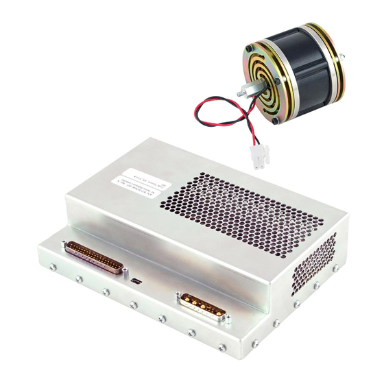
Section 1 Equipment Description System Components The Sunpower Active Vibration Cancellation (AVC) system includes an AVC balancer, AVC controller, over- temp thermistor cable, accelerometer cable, power wiring harness, and instrumentation wiring harness as shown in figure 1. Figure 1. Active Vibration Cancellation (AVC) System Components... -
Page 4: Section 2, Installation
Section 2 Installation Install the AVC Balancer If a passive balancer is attached to the cryocooler, remove the bolt from the middle of the passive balancer and remove the passive balancer from the cryocooler. Now install the AVC balancer as follows: 1. -
Page 5: Install The Accelerometer
Install the Accelerometer Attach the AVC accelerometer (figure 4) (Sunpower part number 300AD-99678-108-015) to the end plate of the CryoTel cryocooler with the provided #5-40 bolt into the end plate of the cryocooler (figure 5). If the cryocooler is an older model not equipped with a #5-40 threaded hole, then use a small amount of super glue to attach the accelerometer onto the end plate in the location shown in figure 5. -
Page 6: Attach The Wiring Harnesses
Attach the Wiring Harnesses The components of the AVC system are interconnected with the cryocooler and with other interfacing equipment using the two supplied wiring harnesses: the power wiring harness, and the instrumentation wiring harness. Power Wiring Harness The power wiring harness (figure 6) has four connections: •... - Page 7 Instrumentation Wiring Harness The instrumentation wiring harness (figure 7) has five connections: • – A molded plastic, 9-pin, female RS-232 serial communications connector that con- Computer Connector nects to an RS-232 serial port on a computer for relaying control commands and replies. •...
-
Page 8: Avc Controller & Over-Temp Thermistor
AVC Controller & Over-Temp Thermistor The AVC controller (figure 8) drives the AVC balancer as well as the cryocooler. A feature of the AVC controller that is not among the features of the standard CryoTel controllers is the reject over-temperature alarm. A provided thermistor (figure 9) is attached to the cooling fins via the available threaded hole (or near the water jacket via thermal epoxy in the case of water cooled systems [figure 10]). - Page 9 Figure 9. Over-Temp Thermistor Cable Figure 10. Thermistor Attached to the Cryocooler with Epoxy Installation & Operation Manual for the Active Vibration Cancellation (AVC) System...
-
Page 10: Section 3, Operation
Section 3 Operation Introduction This section lists all the commands available for use with an AVC controller over the RS-232 interface and re- places the command reference section of the cryocooler user manual. Serial Port Configuration Baud Rate ..9600 Data Bit .... - Page 11 3) Display the current commanded power and power limits a) Command: E<CR> b) The top value is the maximum allowable power for the current temperature. The middle value is the minimum al- lowable power. The bottom value is the current commanded power. All values displayed with this command are in watts.
- Page 12 7) Display the integral constant of the temperature control loop a) Command: KI<CR> b) Returns the integral constant of the temperature control loop. 001.00000 8) Set the integral constant of the temperature control loop a) Command: KI=<VAL><CR> b) This command is User locked. c) <VAL>...
- Page 13 13) Display User lock state a) Command: LOGIN<CR> b) Returns the User lock state. User lock states: 0 – Controller parameters and features mark “User locked” are fully accessible. 1 – Controller parameters and features mark “User locked” are restricted and write protected. LOGIN 001.00 14) Clear User lock state...
- Page 14 18) Set user password a) Command: PASSWD=<VAL><CR> b) This command is User locked. c) A return of 1 confirms the password has been changed. d) <VAL> is the user defined password. The default password is STIRLING. e) The password must be between 1 and 10 characters in length. PASSWD=ABC123 001.00 19) Display the user commanded power...
- Page 15 23) Display the temperature sensor reading in kelvin a) Command: TC<CR> b) Returns the cold head temperature in kelvin. 295.21 24) Display the reject temperature in Celsius a) Command: TEMP<SP>RJ<CR> b) Returns the current reject temperature measured at the base of the fins on the cooler. Reject temperature is displayed in Celsius.
Need help?
Do you have a question about the AMETEK AVC and is the answer not in the manual?
Questions and answers