Table of Contents
Advertisement
Quick Links
Advertisement
Table of Contents

Related Manuals for Measurement Systems International MSI9850


Summary of Contents for Measurement Systems International MSI9850
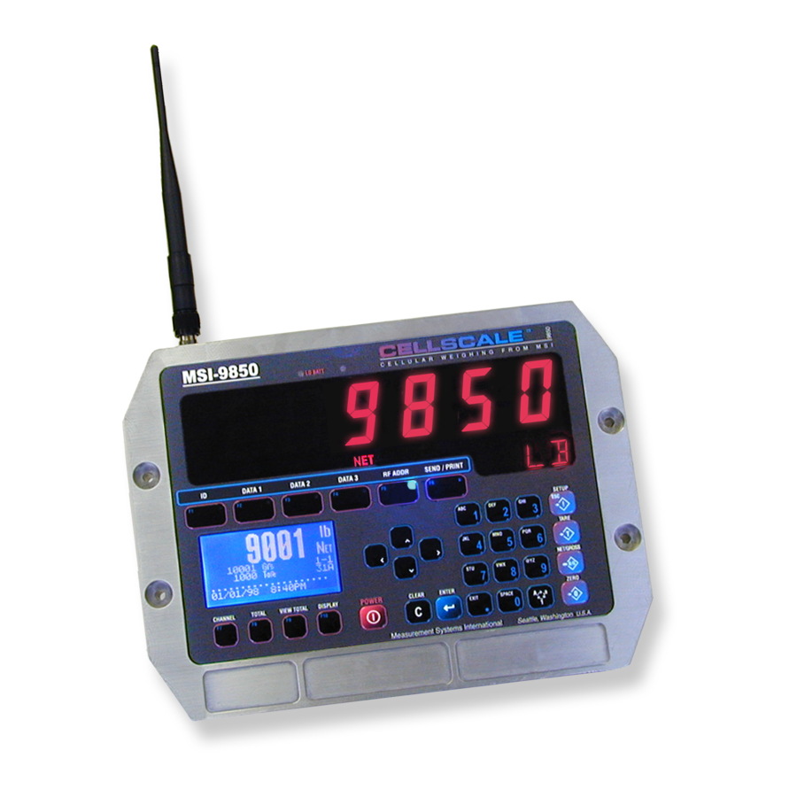
- Page 1 MSI9850 RF Remote Weight Indicator Operator’s Manual...
-
Page 2: Table Of Contents
MSI-9850 HANDHELD RF REMOTE INDICATOR for CALE TABLE OF CONTENTS 1 – I & O ........4 ECTION NTRODUCTION RIENTATION Introduction .................4 MSI-9850 Front Panel ............4 Key Descriptions ..............4 ® 9850 Display Symbols ............6 General Information ............7 Manual & 9850 Conventions ..........7 Features ................8 9850 Block Diagram ............8 cale Family ............9... - Page 3 MEASUREMENT SYSTEMS INTERNATIONAL 6 – I ..............44 A – M ............98 ECTION ODES PPENDIX ID Code Organization ............44 Setup Select Menu ............98 Setup ID Codes Menu ............45 Total Settings ..............98 Using ID Codes ..............46 Password Locks ..............98 ID Code String 1 & String 2 ..........47 Function Keys ..............99 Serial &...
-
Page 4: Section 1 - Introduction & Orientation
CALE SECTION 1 – INTRODUCTION & ORIENTATION INTRODUCTION The Measurement Systems International MSI-9850 RF Remote Indicator is an accessory component of MSI's ® CellScale System. Combined with 1 or more CellScales, the 9850 provides complete control over all scale and ®... - Page 5 MEASUREMENT SYSTEMS INTERNATIONAL key allows entry into the setup submenus. Use this to find menus for setting the Date and Time, setting up SETUP SETUP the function keys, controlling the display mode and backlight, password locks, calibration, etc.. The key is also used for ESCape.
-
Page 6: 9850 Display Symbols
MSI-9850 HANDHELD RF REMOTE INDICATOR for CALE 9850 DISPLAY SYMBOLS ® The 9850 uses a full dot matrix graphics display which allows 3 sizes of fonts and full use of graphic symbols. On standard single channel and multi-channel displays, certain symbols are used for scale specific indications. The motion symbol indicates that the weight has not settled within the motion window (usually ±1d). -
Page 7: General Information
MEASUREMENT SYSTEMS INTERNATIONAL GENERAL INFORMATION The 9850 is a versatile indicator capable of displaying many data items. As a member of the CellScale family the 9850 does not stand alone. It is a slave device to a MSI-9000 CellScale. All data displayed on the 9850 is received via RF from a master CellScale. -
Page 8: Features
MSI-9850 HANDHELD RF REMOTE INDICATOR for CALE FEATURES • Designed to meet or exceed all US and international standards. • Multiple Customized Display Modes, single channel or multiple channel modes ® • Reliable 2.4 GHz Frequency Hopping RF communications. Highly immune to interference and multi-path problems. -
Page 9: The Ell Cale Family
MEASUREMENT SYSTEMS INTERNATIONAL CALE FAMILY 1) Model MSI-9000 CellScale – Rugged unit for interfacing any scale and converting it to RF networking. 2) Model MSI-9008 Multiplexer – Allows up to eight scales with independent calibrations, to share a single CellScale input channel. 3) Model MSI-9020 CellModem –... -
Page 10: Unit Setup
MSI-9850 HANDHELD RF REMOTE INDICATOR for CALE UNIT SETUP The 9850 is simple to setup and use. If there are no peripheral devices such as a printer or bar code scanner, setup consists of applying power, and setting the modem controls to talk to a 9000 CellScale. ®... -
Page 11: 9850 Connectors & Wiring
MEASUREMENT SYSTEMS INTERNATIONAL 9850 CONNECTORS & WIRING The standard configuration of the 9850 has the following connectors: 1) Main Power Input – Usually a heavy duty cable for power input. Available also with a connector by special order. AC and DC power modules are available for all industrial voltage sources. 2) Aux Power and Switches (P2) –... -
Page 12: Main Power Input
MSI-9850 HANDHELD RF REMOTE INDICATOR for CALE MAIN POWER INPUT The 9850 is powered by AC or three choices of DC inputs. Universal AC Supply ® The universal AC Supply is suitable for mains inputs from 86 to 265VAC, 47-440 Hz. The 9850 can be ordered with a standard US Cord (NEMA 5-15 Plug) or an unterminated AC Cord for direct panel wiring or adding a country specific AC Plug. -
Page 13: Aux Power And Switches
MEASUREMENT SYSTEMS INTERNATIONAL Green Connect to Earth Ground. The negative input and earth ground are isolated internally in the 9850. However, the negative output of the Isolated DC supply is common to the chassis ground. Some systems may require isolating the chassis of the 9850 to avoid ground loops. In this case, the Green wire should be insulated and not connected to earth ground. The 9850’s Isolated DC Supply is protected by an internal Fuse. -
Page 14: Serial Ports
MSI-9850 HANDHELD RF REMOTE INDICATOR for CALE SERIAL PORTS Comm Port Cables The 9850 comes standard with one Comm Port Cable wired for RS-232 (MSI P/N 502513-0001) following the ® AT standard for 9 pin serial cables (DCE). An unterminated cable is available (MSI P/N 10084) if you wish to wire your own serial cable for RS-232 or RS-422 or RS-485. -
Page 15: Set Points Output
MEASUREMENT SYSTEMS INTERNATIONAL Both RS-422 and RS-485 are multi-drop capable. COMM 1 RS-422/485 The 9850 can drive up to 32 receivers on one 120Ω Termination twisted pair. Although the 9850 uses standard RS- Resistor (If necessary) 485 drivers, the 9850 firmware does not have a full Jumper 1-6-4 (Optional) duplex protocol. - Page 16 MSI-9850 HANDHELD RF REMOTE INDICATOR for CALE Brown Provides a +5V source for driving relays or auxiliary devices. Fused with a self resetting Polyswitch device. Maximum output current is 500mA total. This output is diode protected and not highly regu- lated as the regulated voltage passes through a Schottky diode.
- Page 17 MEASUREMENT SYSTEMS INTERNATIONAL Interfacing Industry Standard I/O Modules Standard Opto-isolated Output modules are easily driven by the 9850 Output port. MSI provides a 4 port I/O rack prewired with the Set Points Output Cordset (MSI P/N 10082 + 13186). Hooking up the GND wire (Black) is optional when driving output modules.
- Page 18 MSI-9850 HANDHELD RF REMOTE INDICATOR for CALE By combining the Set Points Port P3 with the Switch Input Port P2 a complete I/O interface can be realized. Up to 5 Outputs and 4 inputs can be serviced by the 9850 as illustrated. ®...
-
Page 19: Antennas
MEASUREMENT SYSTEMS INTERNATIONAL ANTENNAS To meet FCC licensing rules, you must use only antennas supplied or recommended by MSI. MSI offers the 9850 with six antenna choices: 1) Standard Antenna – This is a small 1/2 wave antenna that mounts directly on the 9000 CellScale enclosure and is suitable for most short to medium range applications. -
Page 20: Standard Antenna
MSI-9850 HANDHELD RF REMOTE INDICATOR for CALE STANDARD ANTENNA The Standard Antenna (pictured here) is an articulated 1/2 wave 2dBi gain design with a standard TNC connector. This antenna and Coax connector, though resistant to water, is not water-proof. Seal the TNC base with an adhesive heat shrink boot if this antenna is exposed to water. -
Page 21: Yagi Antenna
MEASUREMENT SYSTEMS INTERNATIONAL YAGI ANTENNA A highly directional YAGI Antenna is available by special order. This antennas offers both high gain (15dBi) and controllable transmission patterns. This antenna must be carefully aligned for long distance applications. The Beamwidth of the Yagi is 30°... -
Page 22: Standard Antenna Bulkhead Extensions
MSI-9850 HANDHELD RF REMOTE INDICATOR for CALE STANDARD ANTENNA BULKHEAD EXTENSIONS MSI offers short Coaxial cable assemblies to extend the antenna connector when the CellScale equipment is mounted in an industrial enclosure or to penetrate a metal wall. These Coaxial assemblies are designed for 2.4Ghz use and have TNC Male connectors at both ends. -
Page 23: Section 2 - R Fscale Communications
MEASUREMENT SYSTEMS INTERNATIONAL SECTION 2 – RF SCALE COMMUNICATIONS The 9850 is a component of the MSI CellScale System. The CellScale system uses frequency hopping spread- spectrum RF Modem technology transmitting in the 2.4 GHz ISM band. RF Modems have been problematic as the RF bands are very hostile, corrupted by noise, path loss and inter- fering transmission from other radios. -
Page 24: Rf Network Setup
MSI-9850 HANDHELD RF REMOTE INDICATOR for CALE RF NETWORK SETUP The 9850 is a RF Modem connected device. The RF Modem requires setup to connect to one or more CellScales. The 9850 stores information for all 64 possible networks. Each network setting can be modified with the “Modem Settings Menu”. -
Page 25: Advanced Modem Settings
MEASUREMENT SYSTEMS INTERNATIONAL ADVANCED MODEM SETTINGS The “ADVANCED SETTINGS’ menu provides access to some of the advanced features of the 9850’s RF Modem. These features are not usually needed and should be left to defaults. ADVANCED SETTINGS LOCK OUT KEY 1 Lock Out Key Ø... -
Page 26: Configuring For Multiple Networks
MSI-9850 HANDHELD RF REMOTE INDICATOR for CALE CONFIGURING FOR MULTIPLE NETWORKS The 9850 can access multiple CellScales by switching Networks. A press of the key will change the ADDRESS network allowing the 9850 to monitor and control different scales. Because each CellScale has both a network and a CS address, these must be set up with the “SETUP RF NETWORK”... -
Page 27: Troubleshooting Rf Connection Problems
MEASUREMENT SYSTEMS INTERNATIONAL Modem Defaults CS Address equals Network number (e.g. 12-12, 1-65, 9-9, etc.), unless the network number is below 5, then the CS address equals the Network number + 64. Transmit power set to MED. Time out set to 10 seconds. My Address remains unchanged and is the same in any network. -
Page 28: Rf Site Testing
MSI-9850 HANDHELD RF REMOTE INDICATOR for CALE same network, within transmission range. The new breed of wireless phones (not Cell Phones) operating in the 2.4GHz bands will not jam a CellScale. However the CellScale may be received on the wireless phone and will sound like a background ticking noise. -
Page 29: Section 3 - Scale Operation
MEASUREMENT SYSTEMS INTERNATIONAL SECTION 3 – SCALE OPERATION POWER To Turn On the Power 1) Press and hold for 1 second. The LCD should light and show the MSI POWER POWER Logo. The LED will light all segments for a display test. 2) The LCD then displays “MSI-9850-5”, the Network currently loaded as the active If the system fails Address, and the software version number. -
Page 30: Multi-Channel Systems
MSI-9850 HANDHELD RF REMOTE INDICATOR for CALE TO SELECT THE DISPLAY CHANNEL As mentioned above, the 9850 will access any channels setup in the CellScale. It does this with the “CHAN- NEL” function. Use the key to step from channel to channel as dictated by the Scan list stored in the CHANNEL CellScale. -
Page 31: Zero
MEASUREMENT SYSTEMS INTERNATIONAL To Switch Between Multi-Channel Display and Single Channel Displays 1) Highlight the channel you wish to see in the single channel mode by pressing the UP (^) or DOWN (v) cursor keys. 2) Once highlighted press DISPLAY. The highlighted channel will appear in the single channel mode. 3) Perform any scale function while in the single channel mode. -
Page 32: Tare
MSI-9850 HANDHELD RF REMOTE INDICATOR for CALE the scale will zero. The scale will accept a zero setting over the full Range of the scale (NTEP and other Legal-for-trade models may have a limited zero range). Zero settings above 4% of full scale will subtract from the overall capacity of the scale. For example if you zero out 100 lb. -
Page 33: Setup Tare Menu
MEASUREMENT SYSTEMS INTERNATIONAL Tare - Rules for Use: 1) Only positive gross weight readings can be tared. Weight can be tared in both the NET and GROSS modes. When in the NET mode, the TARE is not cumulative, all the weight is tared off (to Net zero). 2) The motion annunciator must be off. -
Page 34: Net / Gross
MSI-9850 HANDHELD RF REMOTE INDICATOR for CALE NET / GROSS Switches the display between Net and Gross modes. Net Weight is defined as Gross Weight minus a Tare Weight. To Switch Between Net Mode and Gross Mode press the key. NET/GROSS ®... -
Page 35: Display Test
MEASUREMENT SYSTEMS INTERNATIONAL DISPLAY TEST Starts a display test to observe all display characters. The Info and Weight displays cycle through their character sets. Sequences through To Start the Display Test all Fonts and test 1) Press the key followed quickly POWER POWER SETUP... -
Page 36: Section 4 - Function Keys
MSI-9850 HANDHELD RF REMOTE INDICATOR for CALE SECTION 4 – FUNCTION KEYS SETUP FUNCTION KEYS The 9850 has 10 FUNCTION keys that can be programmed to any of several functions. The default functions are: ID, DATA 1, DATA 2, DATA 3, RF ADDRESS, PRINT (Comm 1), CHANNEL, TOTAL, VIEW TOTAL, and ®... -
Page 37: Default Function Keys
MEASUREMENT SYSTEMS INTERNATIONAL DEFAULT FUNCTION KEYS .....F1. When pressed, switches to the next available ID Code defined for the current Next Product ID channel. When preceded by a number, will switch directly to the numbered ID. This always works, even if F6 is programmed for another function......F2. -
Page 38: Available F-Key & Switch Functions
MSI-9850 HANDHELD RF REMOTE INDICATOR for CALE .........R2. Add to Total. Also functions as Total On/ Total Off in Auto-Total modes. Total ......R3. Toggles focus channel between Net and Gross displays. Net/Gross ........R4. Tares current weight and displays Net weight. Tare ........R5. - Page 39 MEASUREMENT SYSTEMS INTERNATIONAL ...Sends the Aux 1 string directly to Comm Port 1. Print Aux to Comm 1 ...Sends the Aux 2 string directly to Comm Port 2. Print Aux to Comm 2 ...Sends both Aux strings to their respective Comm Ports. Print Aux to Comm’s ...Tells the Master CellScale to output its Host 1 output string (CellScale local Comm Send to CSRF Host 1...
- Page 40 MSI-9850 HANDHELD RF REMOTE INDICATOR for CALE ...Allows direct entry of ID String 1 which can be used for any text entries. Enter ID String 1 ...Allows direct entry of ID String 2 which can be used for any text entries. Enter ID String 2 Moved “Start/Stop Comm 1”...
-
Page 41: Custom Function Key Labels
MEASUREMENT SYSTEMS INTERNATIONAL CUSTOM FUNCTION KEY LABELS The “Enter ID String 1” and “Enter ID String 2” function keys provide the user some additional capabilities. When designating a key for these text entry modes, the 9850 brings up a text entry screen that allows you to give a custom 8 character label for the ID String. -
Page 42: Rf Remote Control Option
MSI-9850 HANDHELD RF REMOTE INDICATOR for CALE SECTION 5 – RF REMOTE CONTROL OPTION DESCRIPTION MSI-9850 Series RF Indicators can be equipped with an RF Remote Control (RFRC). The RFRC is a transmit ® only device that can be used to perform basic scale functions. The default switch functions can be changed in the Function Key menus and used for any 9850 programmble functions. -
Page 43: Contention Considerations
MEASUREMENT SYSTEMS INTERNATIONAL CONTENTION CONSIDERATIONS It is important to understand that only one transmitter at a time can be activated within a reception area. While the transmitted signal consists of encoded digital data, only one carrier of any frequency can occupy airspace without contention at any given time. -
Page 44: Section 6 - I Dcodes
MSI-9850 HANDHELD RF REMOTE INDICATOR for CALE SECTION 6 – ID CODES • The CellScale can store 32 ID codes. The 9850 controls which ID Code is in use. • Each ID Code stores a Tare Value, a Total Value, a weighment counter, display mode (Net, Gross, Peak, etc...), ®... -
Page 45: Setup Id Codes Menu
MEASUREMENT SYSTEMS INTERNATIONAL SETUP ID CODES MENU Allows setup of ID Codes. A new ID can be created, the 8 character ID Name can be edited, two 20 character print strings can be assigned to each ID Code. Also any or all IDs can be deleted from this menu. In the Product ID menus the ID, CHANNEL, and keys are active. -
Page 46: Using Id Codes
MSI-9850 HANDHELD RF REMOTE INDICATOR for CALE USING ID CODES To Create a New ID Code (Short method) This procedure assumes the default for ENTER F6 has not been modified by the user. ® 1) Press ENTER, then [F6]. 2) Using the numeric keypad enter a name for the new ID Code. Use the key to select letters as ALPHA required. -
Page 47: Id Code String 1 & String 2
MEASUREMENT SYSTEMS INTERNATIONAL The following procedure deletes all existing ID Codes and any totals and statistics stored in them. To Delete all ID Codes This procedure will delete all the product ID codes and all associated Names, Strings, Totals and Statistics for the current active channel. To delete all product IDs for all channels, you must select a channel using the CHANNEL key, then repeat this procedure for each Channel. -
Page 48: Section 7 - Total / Statistics
MSI-9850 HANDHELD RF REMOTE INDICATOR for CALE SECTION 7 – TOTAL / STATISTICS TOTAL • The 9850 can add independent weighments together and keep a counter of how many weighments were added ® (Totaled). The Weighments counter can be thought of as a box or palette counter. •... -
Page 49: Setup Total Menu
MEASUREMENT SYSTEMS INTERNATIONAL Auto Total Operation 1) Enable the desired Auto Total mode in the “SETUP TOTAL” menu (see “SETUP TOTAL”). Select the “AUTONORM”, “AUTOLOAD”, or the “AUTOPEAK” mode. Exit from the setup menu. 2) Use the key to disable (“TTL OFF”) or enable (“TTL ON”) Auto Total. TOTAL 3) Place the weight to be totaled on the scale. -
Page 50: View Total
MSI-9850 HANDHELD RF REMOTE INDICATOR for CALE To Set the Total Mode The following example assumes the F1 function key is in its default mode of “TOTAL”. 1) Press SETUP. 2) Press the switch or select Total. TOTAL [F1] ® 3) The current Total Mode is shown on selection 1. -
Page 51: Statistics
MEASUREMENT SYSTEMS INTERNATIONAL To Clear the Total Value (Current ID Code only) At any time during the following procedure the EXIT key cancels the Clear operation. Clears ID’s statistics registers as well. 1) Press ∑. The current total is displayed. VIEW 2) Press CLR. - Page 52 MSI-9850 HANDHELD RF REMOTE INDICATOR for CALE View Statistics and Grand Statistics The View Statistics feature uses totaled data from the current ID code in the CellScale to compute statistics. Grand Statistics uses totaled data from all ID codes. Only weight that has been totaled will be used in computing statistics.
-
Page 53: System Setup Menu
MEASUREMENT SYSTEMS INTERNATIONAL SECTION 8 – 9850 SETUP SYSTEM SETUP MENU SETUP SELECT MENU SYSTEM SETTINGS KEYPRESS VOLUME = KEYPRESS VOLUME = SETUP SELECT MENU SYSTEM SETTINGS 1 Function Keys CS SW Version: 2-24 2 Set Points 1 Key Volume is SETUP 3 nz 3 System... -
Page 54: Password Locks
MSI-9850 HANDHELD RF REMOTE INDICATOR for CALE Date Mode – Pressing changes the date mode from MM/DD/YY to DD-MM-YY. Time Mode – Press to change between 24 hour time or 12 hour time with AM/PM indication. Daylite (sic) Saving – Press to select the Daylight Saving mode. -
Page 55: Keyboard Lock
MEASUREMENT SYSTEMS INTERNATIONAL RESET ALL: The following procedure will cause you to lose all setups and will return the 9850 to it’s default settings. Use this procedure only as the last resort of having lost your password. 1) Press followed immediately by (SETUP). -
Page 56: Standard & Custom Display Setup
MSI-9850 HANDHELD RF REMOTE INDICATOR for CALE You can also change the Backlight settings using the UP/DOWN cursor keys to select the parameter, and the LEFT/RIGHT cursor keys to change the value. Setting the LCD Contrast LCD contrast is effected by Temperature, humidity, and viewing angle. The 9850’s LCD is temperature compen- sated and usually does not require adjustment due to temperature variations. - Page 57 MEASUREMENT SYSTEMS INTERNATIONAL Total-Wt-ID ..Shows the Total weight stored in the current ID Code. #-SamplesI ..Shows the number of samples totaled and used for statistics for the current ID Code. IDC ..... The ID Code number in the form xxI. e.g. 2I is ID Code 2. IDName-- ...
- Page 58 MSI-9850 HANDHELD RF REMOTE INDICATOR for CALE Multi-Channel Preset Displays Multi-channel presets use the scan list position to assign channels to specific locations. After selecting the preset multi-channel display, the user can reassign any channel in the scan list to any screen location. The Multi-Channel Preset Displays are described by line numbers 1-8 corresponding to the small font layout.
-
Page 59: Scale Display Setup Menu - Preset Displays
MEASUREMENT SYSTEMS INTERNATIONAL SCALE DISPLAY SETUP MENU – PRESET DISPLAYS The Display Setup Menu provides access to all the display presets, backlight control, function key displays and full display customizing. SCALE DISPLAY SETUP SCALE DISPLAY SETUP BACKLIGHT BACKLIGHT DISPLAY 1 Off (max batt-life) SETUP Shortcut EXIT... -
Page 60: Using Display Setup
MSI-9850 HANDHELD RF REMOTE INDICATOR for CALE USING DISPLAY SETUP The 9850 weight display is a primary means of getting and using CellScale data. The user should always select a single channel weight display mode that provides the information needed. When the CellScale is a multi-channel system, a Multi-Channel display mode should also be selected. -
Page 61: Custom Display Setup
MEASUREMENT SYSTEMS INTERNATIONAL CUSTOM DISPLAY SETUP The 9850 weight display is fully customizable. Both the single channel and multi-channel displays can be custom- ized. All available data types plus custom text can be located anywhere on the screen in any of three font sizes: 1) Large Font –... - Page 62 MSI-9850 HANDHELD RF REMOTE INDICATOR for CALE Screen Formatting The 9850 LCD Screen allows a wide variety of scale display screen setups. The illustrations here demonstrate some of the possibilities. The custom display setup menus control the type and placement of available data types. The LCD is a graphics type organized in rows and columns.
- Page 63 MEASUREMENT SYSTEMS INTERNATIONAL Line Preview The bottom two lines of the Row Setup menu illustrate what the line has programmed into it. Data is displayed in row pairs. For example, while programming row 6, row 5 and 6 will be illustrated. When data from another line is present, as it will be with the large font, the preview area will show as lines.
-
Page 64: Custom Screen Setup Procedure
MSI-9850 HANDHELD RF REMOTE INDICATOR for CALE Selecting Items for Display The custom display setup menus provide access to all the data the scale can provide. When an item is present on the display, it will have an arrow next to its selection number. The length of some data items are fixed, but many have variable lengths. -
Page 65: Custom Single Channel Display Setup Menu
MEASUREMENT SYSTEMS INTERNATIONAL CUSTOM SINGLE CHANNEL DISPLAY SETUP MENU SCALE DISPLAY SETUP ROW X-X XX CHARACTERS SCALE DISPLAY SETUP ROW X-X XX CHARACTERS DISPLAY 1 Product ID SETUP Shortcut EXIT 1 Single Scale Mode 2 Net-Gross-Tare Wt 2 Multi Scale Mode 3 Channel Info 3 Backlight 2min... -
Page 66: Custom Multi-Channel Display Setup Menu
MSI-9850 HANDHELD RF REMOTE INDICATOR for CALE CUSTOM MULTI-CHANNEL DISPLAY SETUP MENU SCALE DISPLAY SETUP ROW X-X XX CHARACTER SCALE DISPLAY SETUP ROW X-X XX CHARACTER SETUP DISPLAY 1 Product ID Shortcut EXIT 1 Single Scale Mode 2 Net-Gross-Tare Wt 2 Multi Scale Mode 3 Channel Info ®... -
Page 67: Section 9 - Set Points
MEASUREMENT SYSTEMS INTERNATIONAL SECTION 9 – SET POINTS INTRODUCTION The CellScale system provides extensive Set Point capabilities. Up to 32 Set Points are available. The CellScale performs the A/D conversions and does limit checking for all the Set Points. The 9850 receives Set Point informa- tion from the CellScale and responds as programmed. -
Page 68: Set Point Setup Menu
MSI-9850 HANDHELD RF REMOTE INDICATOR for CALE SET POINT SETUP MENU There are four ways to program values, operators, and remote relays for Set Points. 1) Use the Terminal Interface Mode at the CellScale, 2) use a 3750CS, 3) use a 9750A, or 4) use the 9850. To Enter the Set Point Setup Menus ®... -
Page 69: Program Set Point Menu
MEASUREMENT SYSTEMS INTERNATIONAL PROGRAM SET POINT MENU 1 SP XX -SPName- To edit Set Point 2 9750 Response See General Text Editing Name 3 Input Source ALPHA Procedure 4 Output Assign 5 Delay XXXXXms 0 F4 Menu 6 Latch 8 ENT Save 7 Force On 8 Formula 9 View... -
Page 70: 9850 Response Menu
MSI-9850 HANDHELD RF REMOTE INDICATOR for CALE 9850 RESPONSE MENU The 9850 responds to set points in three ways: with an audible alarm, a message display, or a message sent to comm port 1. These menus program this response. ® SET POINT SET POINT XX 1 Audible Alarms... -
Page 71: Set Point Formula Menu
MEASUREMENT SYSTEMS INTERNATIONAL SET POINT FORMULA MENU FORMULA OPERATOR 1 FORMULA SP XX OPERATOR 1 SP XX 1 Operator 1 > 2 Value 1 XXXXXXX 1 Greater Than > 3 Val 1 Type GROSS 2 > or Equal >= 4 Dual Value 3 Less Than <... -
Page 72: Section 10 - Communication Ports
MSI-9850 HANDHELD RF REMOTE INDICATOR for CALE SECTION 10 – COMMUNICATION PORTS INTRODUCTION • The MSI 9850 is equipped with two serial input / output ports. The Comm Ports are intended for interfacing ® printers, data loggers, scoreboards, and computers to the 9850 Meter. The real-time clock allows the user to time and/or date stamp any data obtained from the 9850. -
Page 73: Comm Port Select Menu
MEASUREMENT SYSTEMS INTERNATIONAL panel is pressed. The Send / Print key is active in all modes unless disabled with the Function key setup or the Lock Function. defaults to “SEND”. defaults to “PRINT”. The “Motion Check” menu ENTER F4 selection determines if printing is allowed or disallowed when the weight is in motion and/or not stable. 3) Print on CTS (Clear to Send, a RS-232 handshake line) –... - Page 74 MSI-9850 HANDHELD RF REMOTE INDICATOR for CALE SEND/PRINT SETUP SELECT MENU COMM PORT 2 SETUP SELECT MENU COMM PORT 2 1 Function Keys SETUP SELECT MENU SETUP SELECT MENU Shortcut 2 Set Points 1 Enter/Edit Strings 1 Channel & Calibrate SETUP 3 System 2 Output Interval...
-
Page 75: General Text Entry
MEASUREMENT SYSTEMS INTERNATIONAL condition occurs, the print string specified in the “Data Out String” will be output on Comm 1. If the “Motion Check” parameter is set to “ON”, the weight must be stable before the 9850 will output data. If a valid trigger occurs, the 9850 will wait for the next settled (out of Motion) reading before it will output data. -
Page 76: General Text Entry Menu
MSI-9850 HANDHELD RF REMOTE INDICATOR for CALE GENERAL TEXT ENTRY MENU ASCII CHARACTERS PUNCTUATION MENU ASCII CHARACTERS PUNCTUATION MENU 1 Punctuation 2 Printable Symbols ADDRESS ® 3 Control Characters 0 F4 Menu 4 Enter Decimal Char ‘ 512 ENT Save 5 Full Screen 9 “... -
Page 77: Printer / Output Formatting
MEASUREMENT SYSTEMS INTERNATIONAL allows access to characters above 127 (decimal). Characters from 128d to 255d are used for special characters and graphics by many printers. Note that outputting characters above 127d requires that the serial setting for data bits is set to 8 (see serial settings menu). Text strings are edited using the cursor keys and the INS key (alternate function of the [F3] key). -
Page 78: Programming The End Of Line Or Start Of Line Strings
MSI-9850 HANDHELD RF REMOTE INDICATOR for CALE The following diagram shows a typical print string format. The end result of this example produces a printout similar to this: PEARS 4.500 lb 8/15/2002 ® In this example we’ll use control characters to both print in red and expand the characters for “PEARS”. Note: control codes used in this example are unique to a specific printer ( a Star Micronics DP8340) and are used for example only. - Page 79 MEASUREMENT SYSTEMS INTERNATIONAL Press the key rapidly 3 times and the entire string will be erased. Press the ESC key to restore the string as it was. Press to store the empty string. ENTER Description Command Suffix Input Output examples & comments examples *= a space or place holder Reset the host parser...
- Page 80 MSI-9850 HANDHELD RF REMOTE INDICATOR for CALE Description Command Suffix Input Output examples & comments examples *= a space or place holder Print Modem ID xxx where x is the modem ID from 1-254 ® Output ID String 1=ID String 1 String 1 from the current ID.
- Page 81 MEASUREMENT SYSTEMS INTERNATIONAL Description Command Suffix Input Output examples & comments examples *= a space or place holder Output Weight Value and mode @W 1=current weight **20.002*LB***GROSS* Length: 20, fixed. Leading zeros suppressed 2=gross **205.08*KG***GROSS* Length: 20, fixed. Leading zeros suppressed 3=net *1188.50*G****NET*** Length: 20, fixed.
-
Page 82: General Text / Control Character Entry
MSI-9850 HANDHELD RF REMOTE INDICATOR for CALE GENERAL TEXT / CONTROL CHARACTER ENTRY Text or control characters are simply entered into the printer data string. All ASCII characters from 1dec to 127dec can be entered with the exception of the “@” symbol which the 9850 uses for its control characters (enter “@@” to print a single “@”). -
Page 83: Serial Output "@" Commands
MEASUREMENT SYSTEMS INTERNATIONAL SERIAL OUTPUT “@” COMMANDS The printer formatting “@” commands and their data configurations are as follows: Erasing the data logging memory is permanent. The data will be lost. Make sure the data is no longer needed before using the erase memory functions. -
Page 84: Section 11 - Data Logging
MSI-9850 HANDHELD RF REMOTE INDICATOR for CALE SECTION 11 – DATA LOGGING INTRODUCTION The 9850 has two battery backed memory locations for storing scale data. Predefined function keys are available ® for storing user configured data directly to either memory location. Data Logging uses the “Data Out String” and “Aux String”... - Page 85 MEASUREMENT SYSTEMS INTERNATIONAL 5) Erase Memory 2 – Press to erase all data in Memory 2. A caution screen appears requiring confirmation before erasing the data. The line indicates the per cent used capacity of memory 2. It will read “CLR” when empty.
-
Page 86: Section 12 - Text Messaging
MSI-9850 HANDHELD RF REMOTE INDICATOR for CALE SECTION 12 – TEXT MESSAGING The MSI-9850 provides a means for sending messages from host computers directly to the 9850 display. The remote computer uses a host command to send data to any 9850 on the same network (0-63). Once the 9850 receives a text message, it is displayed until a key is pressed. -
Page 87: 9850 To Host Messages
MEASUREMENT SYSTEMS INTERNATIONAL 9850 TO HOST MESSAGES Once a sent message is observed by the 9850 user, pushing any key will clear the message and return the 9850 to the last display mode. An acknowledgment string is automatically sent back to the modem that generated the message. -
Page 88: Section 13 - Bar Code
MSI-9850 HANDHELD RF REMOTE INDICATOR for CALE SECTION 13 – BAR CODE The Bar Code features of the 9850 allow the user to add scanned data to weight readings and trigger transmis- sions directly into RF connected computers. In combination with the Data Logging features, bar code scans can trigger data storage for uploading later. - Page 89 MEASUREMENT SYSTEMS INTERNATIONAL BAR CODE SETUP MENU SETUP SELECT MENU SETUP SELECT MENU BAR CODE SETUP MENU 1 Function Keys 1 Bar Code 1 Buffer 2 Set Points 2 Bar Code 2 Buffer SETUP 3 System 3 Bar Code 3 Buffer 4 Password Locks 4 Bar Code 4...
-
Page 90: Section 14 - Channel Setup & Calibration
MSI-9850 HANDHELD RF REMOTE INDICATOR for CALE SECTION 14 – CHANNEL SETUP & CALIBRATION CHANNEL SETUP MENU CHANNEL / CALIBRATION CHANNEL / CALIBRATION 1 Channel is ACTIVE --Channel Name-- --Channel Name-- --Chn-- --Chn-- --Index-- --Index-- ® CHANNEL SETUP 1 Channel INACTIVE Shortcut 1 Channel is... -
Page 91: Calibrate General Information
MEASUREMENT SYSTEMS INTERNATIONAL CALIBRATE GENERAL INFORMATION The following sections are intended for qualified scale technicians. The CellScale can be calibrated either directly using the Terminal Interface mode, or by using a 9850 or 3750CS. See the CellScale operators guide for informa- tion on direct calibration. - Page 92 MSI-9850 HANDHELD RF REMOTE INDICATOR for CALE CHANNEL / CALIBRATION ENTER to CHANNEL / CALIBRATION --Channel Name-- --Channel Name-- Recalibrate --Chn-- --Chn-- --Index-- --Index-- CHANNEL SETUP Shortcut 1 Channel is ACTIVE CLR to Reset Cal 2 Filter ® 3 Calibrate Settings ESC to Exit Cal 4 Start Calibration 5 Zero RUSure Msg ON...
-
Page 93: To Enable / Disable Azm (Auto Zero Maintenance)
MEASUREMENT SYSTEMS INTERNATIONAL TO ENABLE / DISABLE AZM (AUTO ZERO MAINTENANCE) AZM is used to adjust out variations at zero caused by debris or water on the scale, temperature drift, and any other minor variation that affects the zero setting. Typically AZM is set to 0.5d or 1d, which is adequate for most modern scale systems. -
Page 94: Center-Of-Zero (Coz) Indicator
MSI-9850 HANDHELD RF REMOTE INDICATOR for CALE CENTER-OF-ZERO (COZ) INDICATOR The COZ indicator turns on when the scale is within 1/4 d of the last zero setting. Some legal-for-trade jurisdic- tions require its use. To Enable/Disable the COZ Indicator ® Before starting the following procedure, you must be in the Top Menu Level of Calibration. -
Page 95: Installing Firmware Updates
MEASUREMENT SYSTEMS INTERNATIONAL INSTALLING FIRMWARE UPDATES The 9850 contains Flash memory that allows the firmware to be upgraded through the Comm Port. A “Boot Loader” program is used to load a new program file into the 95750. MSI will update and improve the 9850 feature set over time and provide program updates free of charge. - Page 96 MSI-9850 HANDHELD RF REMOTE INDICATOR for CALE _+)#!!!_+)#!!!_+)#!!!_+)#!!!_+)#!!!_+)#!!!_+)#!!!_+)#!!!_ #!!!_+)#!!!_+)#!!!_+)#!!!_+)#!!!_+)#!!!_+)#!!!_+)#!!!_+)# before matching baud rates after matching baud rates When you can read this, press any key. ® When you can read this, press any key. When you can read this, press any key. MSI Boot Loader Version 3.K3 Update Application Change Baud Rate...
-
Page 97: 9850 Setup Duplicating
5) On the source unit (the one already configured), press SETUP, SEND/PRINT, [4], [4], [4]. 6) On the receiving unit, press SETUP, SEND/PRINT, [4], [4], [4], (Display key). EXIT 7) If the receiving unit is not displaying “MSI9850-5” press POWER followed quickly by ESC. 8) Press on the receiving unit. 9) Press on the source unit. -
Page 98: Appendixa - Menu Maps
MSI-9850 HANDHELD RF REMOTE INDICATOR for CALE APPENDIX A – MENU MAPS SETUP SELECT MENU SETUP SELECT MENU SETUP SELECT MENU SETUP SELECT MENU SETUP SELECT MENU ® 1 Function Keys 1 Channel & Calibrate 2 Set Points 2 Display SETUP 3 System 3 RF Modem... -
Page 99: Function Keys
MEASUREMENT SYSTEMS INTERNATIONAL FUNCTION KEYS SETUP SELECT MENU FUNCTION KEY ASSIGNS ENTER-FKEY ASSIGNS ENTER-FKEY ASSIGNS SETUP SELECT MENU FUNCTION KEY ASSIGNS 1 Function Keys 1 F1 is Add to Total 1 E1 is Clr Last ∑ 2 Set Points 2 F2 is Next Channel 2 E2 is Back Channel SETUP 3 System... -
Page 100: Serial & Strings
MSI-9850 HANDHELD RF REMOTE INDICATOR for CALE SERIAL & STRINGS SEND/PRINT SETUP SELECT MENU COMM PORT 2 SETUP SELECT MENU COMM PORT 2 1 Function Keys ® SETUP SELECT MENU SETUP SELECT MENU Shortcut 2 Set Points 1 Enter/Edit Strings 1 Channel &... -
Page 101: Product Id Codes
MEASUREMENT SYSTEMS INTERNATIONAL PRODUCT ID CODES SETUP SELECT MENU SETUP SELECT MENU PRODUCT ID Chan SETUP SELECT MENU SETUP SELECT MENU PRODUCT ID Chan X-X 1 Function Keys 1 Channel & Calibrate Net XX IDName-- 2 Set Points 2 Scale Display Line 1 New Product ID SETUP 3 System... -
Page 102: Tare Settings
MSI-9850 HANDHELD RF REMOTE INDICATOR for CALE TARE SETTINGS TARE SETTINGS TARE SETTINGS -CHANNEL NAME or NUM- TARE SETUP Shortcut 1 Disable Auto Clear 2 Set Clear on Minus ® 3 Set Clear on Total 4 Tare by Product ID 5 Same Tare All ID’s RF MODEM SETTINGS MODEM SETTINGS... -
Page 103: Scale Display Setup
MEASUREMENT SYSTEMS INTERNATIONAL SCALE DISPLAY SETUP BACKLIGHT BACKLIGHT SCALE DISPLAY SETUP SCALE DISPLAY SETUP DISPLAY 1 Off (max batt-life) SETUP Shortcut EXIT 1 Single Scale Mode 2 On for 15 seconds 2 Multi Scale Mode 3 On for 30 seconds 4 On for 1 minute 3 Backlight 2min... -
Page 104: Scale Single Channel Custom Display Setup
MSI-9850 HANDHELD RF REMOTE INDICATOR for CALE SCALE SINGLE CHANNEL CUSTOM DISPLAY SETUP SCALE DISPLAY SETUP ROW X-X XX CHARACTERS SCALE DISPLAY SETUP ROW X-X XX CHARACTERS DISPLAY 1 Product ID SETUP Shortcut EXIT 1 Single Scale Mode 2 Net-Gross-Tare Wt ®... -
Page 105: Scale Multi-Channel Custom Display Setup
MEASUREMENT SYSTEMS INTERNATIONAL SCALE MULTI-CHANNEL CUSTOM DISPLAY SETUP SCALE DISPLAY SETUP ROW X-X XX CHARACTER SCALE DISPLAY SETUP ROW X-X XX CHARACTER DISPLAY SETUP 1 Product ID Shortcut EXIT 1 Single Scale Mode 2 Net-Gross-Tare Wt 2 Multi Scale Mode 3 Channel Info 3 Backlight 2min... -
Page 106: Channel / Calibrate Settings
MSI-9850 HANDHELD RF REMOTE INDICATOR for CALE CHANNEL / CALIBRATE SETTINGS CHANNEL / CALIBRATION 1 Channel is ACTIVE CHANNEL / CALIBRATION --Channel Name-- --Channel Name-- --Chn-- --Index-- --Chn-- --Index-- CHANNEL SETUP 1 Channel INACTIVE Shortcut 1 Channel is ACTIVE 2 Filter 3 Calibrate Settings ®... -
Page 107: System Settings
MEASUREMENT SYSTEMS INTERNATIONAL SYSTEM SETTINGS SETUP SELECT MENU SYSTEM SETTINGS KEYPRESS VOLUME = KEYPRESS VOLUME = SETUP SELECT MENU SYSTEM SETTINGS 1 Function Keys CS SW Version: 2-24 1 Key Volume is 2 Set Points SETUP 3 nz 3 System 2 Alarm Volume is 4 nn 8 nnnn... -
Page 108: Calibration
MSI-9850 HANDHELD RF REMOTE INDICATOR for CALE CALIBRATION CHANNEL / CALIBRATION ENTER to CHANNEL / CALIBRATION --Channel Name-- --Channel Name-- Recalibrate --Chn-- --Chn-- --Index-- --Index-- CHANNEL SETUP Shortcut 1 Channel is ACTIVE CLR to Reset Cal 2 Filter ® 3 Calibrate Settings ESC to Exit Cal 4 Start Calibration 5 Zero RUSure Msg ON... -
Page 109: General Text Entry
MEASUREMENT SYSTEMS INTERNATIONAL GENERAL TEXT ENTRY ASCII CHARACTERS PUNCTUATION MENU ASCII CHARACTERS PUNCTUATION MENU 1 Punctuation 2 Printable Symbols ADDRESS 3 Control Characters 0 F4 Menu 4 Enter Decimal Char ‘ 512 ENT Save 5 Full Screen 9 “ 6 Size SMALL 21/ROW -NAMEofSTRING- Show 83 Characters... -
Page 110: Set Points
MSI-9850 HANDHELD RF REMOTE INDICATOR for CALE SET POINTS Input Set Point MASTER SET POINTS PROGRAM SET POINT ® MASTER SET POINTS PROGRAM SET POINT 1 SP XX -SPName- # for programming ESC exits no change 2 9750 Response (1-32) 1 Program Set Point ENTER edits value 3 Input Source... -
Page 111: Appendixb - Ascii C
MEASUREMENT SYSTEMS INTERNATIONAL APPENDIX B – ASCII CHART Firmware Version 5-XX for 2450 Modems ® MSI CellScale System • 9850 User Guide Page 111... -
Page 112: Appendixc - Specifications & Summary Of Features
MSI-9850 HANDHELD RF REMOTE INDICATOR for CALE APPENDIX C – SPECIFICATIONS & SUMMARY OF FEATURES Temperature Range Display ® • 64 x 128 Full Graphics Module • -20° C to +70° C Operating (-4° F to 158° F) • Multiple Font sizes, up to 8 lines of 21 characters •... - Page 113 THE MSI LIMITED WARRANTY MEASUREMENT SYSTEMS INTERNATIONAL, INC., WARRANTS load sensing elements and meters against defects in workmanship and materials for a period of one year from date of purchase and warrants electrical cables and batteries against the same defects for a period of ninety (90) days from date of purchase.
- Page 114 Measurement Systems International A RICE LAKE WEIGHING SYSTEMS COMPANY 14240 Interurban Avenue South Suite 200 Seattle, WA 98168-4661 Phone: 206-433-0199 Fax: 206-244-8470 www.msiscales.com © 2012 Rice Lake Weighing Systems...
Need help?
Do you have a question about the MSI9850 and is the answer not in the manual?
Questions and answers