Table of Contents
Advertisement
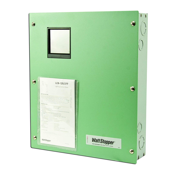
UNIT DESCRIPTION
The LC8 Lighting Control Panel is an easy to use lighting controller intended for
applications where automated lighting control is required. Lighting control can be
configured to respond to scheduling, photocell input, astronomic input, switch input and/
or combinations of these. The LC8 is suitable for interior or exterior lighting and can be
configured with either single pole single throw relays or double pole single throw relays
for multi pole circuits. Configuration changes are easily made through the integrated
touch screen that is always accessible through the panel cover.
SPECIFICATIONS
Power input. . . . . . . . . . . . . . . . . . . . . . . 120/277 VAC; 50/60 Hz
Accessory power. . . . . . . . . . . . . . . . . . . 500 mA at 24 VDC
Switch inputs with screw terminals;
Used with 3-wire momentary, 2-wire momentary or maintained with pilot light output
Relay grouping
Configurable to switches through touchscreen user interface
Panel weight . . . . . . . . . . . . . . . . . . . . . . 8.1 lbs. (without relays)
Relays . . . . . . . . . . . . . . . . . . . . . . . . . . . Modular; dual 1-pole or single 2-pole
LCDP-1 relay ratings
Ballast/LED Driver. . . . . . . . . . . . . . . 20 A @ 208V
Ballast/LED Driver. . . . . . . . . . . . . . . 20 A @ 240V/480V (2 Phase)
Motor. . . . . . . . . . . . . . . . . . . . . . . . . . 1 HP @ 208V/240V
Short Circuit Current Rating. . . . . . . 14kA AIC @ 277 VAC
LCSP-2 relay ratings
Incandescent . . . . . . . . . . . . . . . . . . 20 A @ 120V/277V
Ballast/LED Driver . . . . . . . . . . . . . . 20 A @ 120V/277V
Motor . . . . . . . . . . . . . . . . . . . . . . . . . 1/2 HP @ 120V
Short Circuit Current Rating. . . . . . . 14kA AIC @ 277 VAC
Relay weight . . . . . . . . . . . . . . . . . . . . . . LCDP-1: 0.49 lbs., LCSP-2: 0.37 lbs.
Operating conditions . . . . . . . . . . . . . . . For indoor use only
UL and CUL listed
LC8-120/277
Lighting Control Panel
32-122
F (0-50
C); 5-95% RH noncondensing
o
o
©2013 WattStopper
Advertisement
Table of Contents

Summary of Contents for Watt Stopper LC8-120/277
- Page 1 LC8-120/277 Lighting Control Panel UNIT DESCRIPTION The LC8 Lighting Control Panel is an easy to use lighting controller intended for applications where automated lighting control is required. Lighting control can be configured to respond to scheduling, photocell input, astronomic input, switch input and/ or combinations of these.
-
Page 2: Table Of Contents
TABLE OF CONTENTS Quick Setup....................3 Interior Lighting..................3 Exterior Lighting..................6 Installation and Setup.................10 Installing the Panel................10 Wiring SPST Loads.................11 Wiring DPST Loads.................12 Connecting Low Voltage Switches to the LC8..........12 Connecting Occupancy Sensors and Photocells........13 Connecting an EM24-D Exterior Photocell to the LC8......13 Operation Guide..................14 Theory of Operation................14 Icon Definitions..................14... -
Page 3: Quick Setup
QUICK SETUP The LC8 is designed to allow very flexible automated lighting control yet can be set up to do basic automatic control functions very simply. It is assumed that your unit is installed and wired before using this Quick Setup. The steps for basic control are as follows: Interior Lighting The following example provides quick setup instructions for assigning interior lighting to a schedule. - Page 4 Assign Relay 1 8 to Select relay number to highlight Channel A H - Touch relay number again to select Channel A - Repeat above for all desired relays - Select Save Note: In the example only relay 1 controls interior lighting and has been assigned to Chan- nel A.
- Page 5 Schedule Time - 1 Set Schedule 01 Schedule ON/OFF : 00 ON 00 : 00 OFF 00 : 00 ON 00 : 00 OFF 00 : 00 Off: 00 : 00 Blink Before Off Time Delay 000 Min Touch hours (and minutes Select Save to save if desired) to highlight.Use...
-
Page 6: Exterior Lighting
Assign Schedule/Channel Local - Channel A Set [Sun] Sch01 [Mon] None [Tue] None [Wed] None [Thu] None [F r i ] None [Sat] None [Hol] None Enter Sch01 to each day of The Assign Schedule/ the week desired. Select Channel menu displays. Save Select Channel A Result: Interior lighting will turn ON at the scheduled ON time and turn OFF at the sched-... - Page 7 Step 2: Enter Geographic Location Home Setup Setup Set Time And Date Schedules Setting 02/07/11 Daylight Saving Time Program Holiday 20 : 12 : 40 Assign Relays/Input Select Location Assign Relays/Channel Sound Options Sunrise 06:39 Assign Schedule/Channel Sunset 17:24 Select Next Select Setup from Schedules Setting displays...
- Page 8 Assign Relay 1 8 to Channel A H - Select relay # to highlight - Touch relay number again to select Channel B - Repeat above for all desired relays - Select Save Step 4: Set a Schedule Home Setup Setup 02/07/11 Set Time And Date...
- Page 9 Step 5: Assign Channel to your Schedule Home Setup Setup 02/07/11 Set Time And Date Set Time And Date Daylight Saving Time Daylight Saving Time 20 : 12 : 40 Assign Relays/Input Assign Relays/Input Assign Relays/Channel Assign Relays/Channel Sunrise 06:39 Assign Schedule/Channel Assign Schedule/Channel Sunset 17:24...
-
Page 10: Installation And Setup
Fig.1: LC8 Components Installing the Panel The LC8-120/277 enclosure is designed for surface wall mounting. Attach the enclosure to the wall using hardware appropriate for the wall type and material (not included). The relays for the LC8 are modular and may have shipped separately from the enclosure. -
Page 11: Wiring Spst Loads
To Relay Module LCPS-120/277 Ground GROUND LED lit when 120/277VAC power is on. 50/60Hz 24VDC, 0.5A Class 2 Output Ground Power Supply for use with Release LC8 Lighting Control Panel Button Use Copper Conductors Only LINE AC Input 86WA NEUTRAL Pat. -
Page 12: Wiring Dpst Loads
Wiring DPST Loads 1. Connect the load wires to the Output 1 and Output 2 terminal blocks on the LCDP-1 double pole relay module. 2. Connect the double pole circuit to be controlled to the Input 1 and Input 2 terminal blocks. 3. -
Page 13: Connecting Occupancy Sensors And Photocells
Jumper between B and +24 - Pilot - On - Off WHITE - +24 - Gnd 2-Wire Momentary Push Button - Pilot - On WHITE - Off - +24 BLACK - Gnd Standard 3-Wire Momentary B -to- W Jumper - Pilot - On - Off WHITE... -
Page 14: Operation Guide
OPERATION GUIDE Theory of Operation The LC8 lighting control panel is designed to automatically control interior or exterior lighting based on a weekly schedule, astronomic time calculation or input from an accessory photocell. Automatic operation can be augmented or overridden through the use of accessory low volt- age wall switches. -
Page 15: Getting Started
Getting Started Upon initial start up, the Logo screen is displayed: Touch Screen to Start Touch the screen to display the Home menu: Home 02/07/11 20 : 12 : 40 Sunrise 06:39 Sunset 17:24 The Home screen always displays the current day of the week, date, Daylight Savings Time (DST) status and the time of day in 24 hour format. -
Page 16: Relays Override
Relays Override Home Local - Relays 02/07/11 20 : 12 : 40 Sunrise 06:39 Sunset 17:24 Touch Rotate Touch a Relay to toggle the display the Local-Relays relay ON and OFF screen Note that two pole relays will be controlled by the odd number, or first, relay position. The even number position will be blank. -
Page 17: Setup Menus
Setup Menus There are three setup menus that you can cycle through: Setup Setup Home 02/07/11 Set Time And Date Schedules Setting Daylight Saving Time Program Holiday 20 : 12 : 40 Assign Relays/Input Select Location Assign Relays/Channel Sound Options Sunrise 06:39 Assign Schedule/Channel Sunset 17:24... -
Page 18: Daylight Saving Time
Daylight Saving Time The LC8 can be set to follow or not follow DST. Home Setup Setup Set Time And Date Set Time And Date 02/07/11 Daylight Saving Time Daylight Saving Time 20 : 12 : 40 Assign Relays/Input Assign Relays/Input Assign Relays/Channel Assign Relays/Channel Sunrise 06:39... -
Page 19: Assigning Relays To An Input
Assigning Relays to an Input Setup Setup Home 02/07/11 Set Time And Date Set Time And Date Daylight Saving Time Daylight Saving Time 20 : 12 : 40 Assign Relays/Input Assign Relays/Input Assign Relays/Channel Assign Relays/Channel Sunrise 06:39 Assign Schedule/Channel Assign Schedule/Channel Sunset 17:24 The Setup menu displays... -
Page 20: Assigning Relays To Channels
Assigning Relays to Channels Home Setup Setup 02/07/11 Set Time And Date Set Time And Date Daylight Saving Time Daylight Saving Time 20 : 12 : 40 Assign Relays/Input Assign Relays/Input Assign Relays/Channel Assign Relays/Channel Sunrise 06:39 Assign Schedule/Channel Assign Schedule/Channel Sunset 17:24 Select Setup from... -
Page 21: Assigning Schedules To Channels
Assigning Schedules to Channels Setup Setup Home 02/07/11 Set Time And Date Set Time And Date Daylight Saving Time Daylight Saving Time 20 : 12 : 40 Assign Relays/Input Assign Relays/Input Assign Relays/Channel Assign Relays/Channel Sunrise 06:39 Assign Schedule/Channel Assign Schedule/Channel Sunset 17:24 Select Setup from... - Page 22 Schedules Schedule 01 Schedule 01 Schedule ON/OFF Schedule ON/OFF [Sch01] [Sch02] [Sch03] [Sch04] ON 00 : 00 OFF 00 : 00 ON 00 : 00 OFF 00 : 00 [Sch05] [Sch06] [Sch07] [Sch08] ON 00 : 00 OFF 00 : 00 ON 00 : 00 OFF 00 : 00 [Sch09]...
-
Page 23: Manual On/Schedule Off
Manual ON/Schedule OFF Time settings will turn the lighting OFF. Lighting will be turned ON manually. This setting works similar to Schedule ON/OFF, except that the ON time setting does not turn the light- ing ON. It determines the time when the Time Delay feature is deactivated. Home Setup Setup... -
Page 24: Astronomic & Schedule On/Off
Schedule 01 Time Delay Manual ON/Sched OFF ON 00 : 00 OFF 00 : 00 ON 00 : 00 OFF 00 : 00 000 Min Blink Before Off Time Delay 000 Min Use up and down arrows to set Touch time delay to display number of minutes between OFF Time Delay screen sweeps... -
Page 25: Photocell & Schedule On/Off
Schedule 01 Time Offset Astro & Sched ON/OFF ON 00 : 00 OFF 00 : 00 ON 00 : 00 OFF 00 : 00 000 Min Blink Before Off Time Offset 000 Min Touch Time Offset. Touch Use up and down arrows to set again to set sunrise or number of minutes for Time sunset offset. -
Page 26: As-100 Auto On/Off
Schedules Schedule 01 Schedule 01 Photo & Sched ON/OFF Photo & Sched ON/OFF [Sch01] [Sch02] [Sch03] [Sch04] ON 00 : 00 OFF 00 : 00 ON 00 : 00 OFF 00 : 00 [Sch05] [Sch06] [Sch07] [Sch08] ON 00 : 00 OFF 00 : 00 ON 00 : 00 OFF 00 : 00... -
Page 27: As-100 Manual On/Auto Off
Schedule 01 Time Repeat AS Auto ON/OFF ON 00 : 00 OFF 00 : 00 ON 00 : 00 OFF 00 : 00 000 Min Repeating Off 000 Min Touch Repeating Off twice Use up and down arrows to set to enter Time Repeat number of minutes between OFF screen... - Page 28 Setup Home Setup 02/07/11 Set Time And Date Schedules Setting Daylight Saving Time Program Holiday 20 : 12 : 40 Assign Relays/Input Select Location Assign Relays/Channel Sound Options Sunrise 06:39 Assign Schedule/Channel Sunset 17:24 Select Setup from Select Next Schedules Setting displays from Home menu Setup Holiday set (page 1 )
-
Page 29: Setting A Location For The Astronomic Feature
Setting a Location for the Astronomic Feature Home Setup Setup 02/07/11 Set Time And Date Schedules Setting Daylight Saving Time Program Holiday 20 : 12 : 40 Assign Relays/Input Select Location Assign Relays/Channel Sound Options Sunrise 06:39 Assign Schedule/Channel Sunset 17:24 Select Setup from Select Next... -
Page 30: Sound Options
Sound Options Setup Home Setup 02/07/11 Set Time And Date Schedules Setting Daylight Saving Time Program Holiday 20 : 12 : 40 Assign Relays/Input Select Location Assign Relays/Channel Sound Options Sunrise 06:39 Assign Schedule/Channel Sunset 17:24 Select Next Select Setup from Schedules Setting displays the Home menu... -
Page 31: Troubleshooting
Restore Fact.Default Setup Restore Fact. Default You are about to clear all Memory to factory default. Touch the Yes key to clear all memory and return to main menu. [Yes] [No] Touch Restore Fact. Default Confirm the action by touching Yes. To cancel the action and return to the menu, touch No TROUBLESHOOTING... -
Page 32: Lighting Control Panel Circuit & Program Documentation Form
Lighting Control Panel Circuit & Program Documentation Form Switch Controlled Relays or Relay Load Description Assigned Input Controlled Channel Pole Channel Channel Letters below left correspond to Channel letters above right Channel Enter the schedule numbers that apply in the spaces above WARRANTY INFORMATION WattStopper warranties its products to be free of defects in materials and workmanship for a period of five (5) years.
Need help?
Do you have a question about the LC8-120/277 and is the answer not in the manual?
Questions and answers