Table of Contents

Related Manuals for Artos Engineering Company CS 338

Summary of Contents for Artos Engineering Company CS 338
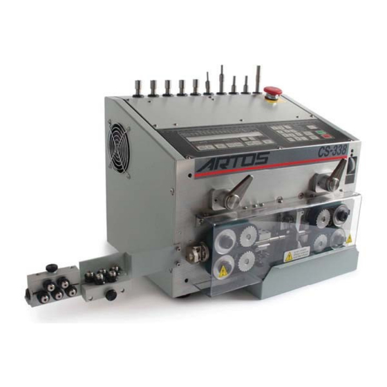
- Page 1 Machine Model CS 338 Wire Processor Owners Manual 6-119906 Rev. 3.1 Date 30 Oct 2013 Artos Engineering Company 21605 Gateway Court Brookfield, WI 53045 Phone 1 262 252 4545 Fax 1 262 252 4544 www.artosnet.com service@artosnet.com PN 6-119906 - 1 -...
-
Page 2: Table Of Contents
Table of Contents Table of Contents _________________________________________________________ 2 Introduction _____________________________________________________________ 4 Technical Data ___________________________________________________________ 4 Description __________________________________________________________________ 4 Warning and Safety Instructions ____________________________________________ 4 Unpacking: ______________________________________________________________ 5 OPTIONS _______________________________________________________________ 5 BLADES: ___________________________________________________________________ 5 BELTS: ____________________________________________________________________ 5 Pre Process__________________________________________________________________ 5 Prefeeders __________________________________________________________________ 5 Operator Control Features _________________________________________________ 6 Set Up __________________________________________________________________ 7 Wire Straightener Installation __________________________________________________ 7... - Page 3 Voltage Selection ____________________________________________________________ 24 PN 6-119906 - 3 -...
-
Page 4: Introduction
Introduction Your ARTOS Wire Processor accurately measures, cuts, strips and counts various wires. It is the perfect choice for your flexible wire processing needs and portable manufacturing requirements. The user friendly electronic controls allow anyone to program the ARTOS Wire Processor with no training. The system will prompt you through each step of the operating parameters. -
Page 5: Unpacking
Unpacking: The following parts should be included with the machine. Wrench set 691.020 Feed tubes set 2-144434 Power Cord 916-445 110VAC Wire striaghener IA-4379 916-446 220VAC Guard 5-143390 Scrap tray 143387 Calibration tool K-8685 OPTIONS BLADES: Spare blade Set LB-1253 (Pair) Std. Spare blade Set LB-1725 (Pair) Coated for long life. -
Page 6: Operator Control Features
Operator Control Features On-Off Switch (Power Module) is located on the back of the case. This contains machine fuses. Fuses are also used to change voltage selection. Be sure the fuses are installed properly for the voltage it is being connected to. See page 19 “Voltage Selection” Turns main power on ( I ) and off ( O ). -
Page 7: Set Up
Install Wire Straightener using two of the #8-32 screws provided. Selecting and Changing Guide Tubes The CS 338 comes with a set of 5 matched guides. LA-4041 “A” Middle Guide 060(1.5mm) L.A-3986 “A” Rear Guide .060(1.5mm) LA-4042 “B” Middle Guide .100(2.5mm) LA-3987 “B”... -
Page 8: Loading Wire
Loading Wire To load the wire simply rotate the feed belt levers Counterclockwise. This will hold the belts open. 1. Insert the wire thru the wire Straightener 2. Then open the feed belts by turning the levers to the left. Feed the wire thru the wire run out assembly using the proper size hole between the infeed belts. - Page 9 Thumbwheel Loading wire continued Left On the outfeed, adjust the outfeed stop Thumbwheel so the belts close to a gap equal to or slightly smaller than the conductor of the wire after stripping. This will allow the leading end of the wire to start between the belts without stubbing the end back.
- Page 10 Controls The CS 338 uses a membrane push button panel to set the perimeters for cutting your wire. The functions by button are: 1. Wire length, set overall wire length 2. Left strip, set left or trailing strip length 3. Left strip pull, pull length of left strip 4.
-
Page 11: Typical Programming Sequence
Display (Run Screen) The CS 338 displays the cutting information on the LCD screen. That information is as follows: A. Left strip B. Left pull C. Cut length D. Right pull E. Right strip F. Ready status G. Center strip active H. -
Page 12: Mode Selection
Mode Selection The CS 338 has several options that can be invoked. These are accessed by pressing the Select Button. The options and functions that are available are: PART PROGRAM MODE SPEED CALIBRATION INCH /METRIC PART The Part Program function allows you to store up to 99 wire programs. This includes the length and strip values as well as marking options if selected. -
Page 13: Program Mode
PROGRAM MODE Press select until: PRESS ENTER FOR PROGRAM MODE Press the select button until the “PROGRAM MODE” is displayed Press “ENTER” 1 - LANGUAGE 2 - WIRE (LONG/SHORT) 3 - WIRE MARKING 4 - WIRE OUT SENSOR In “PROGRAM MODE” you can choose to change a language, the short/long wire operation, wire marking, or wire run-out detection by selecting the appropriate number. - Page 14 ENTER IN DWELL TIME Select 1 , and enter the dwell time (the marking time) press ENTER 1 – END MARKING 2 - CONTINUOUIS Select 1 for end marking (a mark on each end of the wire) press ENTER You will be asked to select the type of marker used. One type-set or 2 type-set marker, select the correct one and press ENTER.
-
Page 15: Programming Center Strip Function
Programming Center Strip Function Press the SELECT key or until the ‘PROGRAM MODE” window appears and PRESS ENTER FOR PROGRAM MODE In “PROGRAM MODE”, you can choose to change a language, select the short/long wire operation, wire marking, or wire run-out detection by selecting the appropriate number. Select the “2 WIRE”. -
Page 16: Speed
SPEED Press select until: PRESS ENTER TO CHANGE FEED SPEED Selecting the feed change function allows you to change the feed speed of the machine for minimum to maximum in 10 steps. - TO DECREASE + TO INCREASE LOW > <... -
Page 17: Wire Calibration And Part Program Relationship
WIRE CALIBRATION AND PART PROGRAM RELATIONSHIP WIRE CALIBRATION Different wires require different wire calibrations. This is due to the differences in outside diameter, insulation smoothness and drag caused by the straightener or the de-reeler. The calibration is a multiplier to determine the wire length. - Page 18 PRESS KEY FOR CALIBRATION SELECTION 1 - BLADE 2 - WIRE LENGTH 3 - STRIP Select 1 to calibrate the blades. You will need the blade calibration tool shown below. Round end is for tightening the blade holders Square end is for Calibration tool in place blade calibration + TO OPEN BLADES...
-
Page 19: Part Program Store / Recall Procedure
ADDITIONAL LEFT STRIP LENGTH 1=0.006 INCH OR 0,15 MM ADDITIONAL RIGHT STRIP LENGTH 1=0.006 INCH OR 0,15 MM Select 3 to calibrate the strip length. Cut and strip a wire. Keep track of left, tail end and right, lead end of the wire. Measure the strip length. -
Page 20: Inch/Metric
INCH/METRIC Press select until: PRESS ENTER TO CHANGE LENGTHH MODE Press ENTER 1 -- ENGLISH 2 -- METRIC Select 1 display in INCH Select 2 to display in METRIC. PN 6-119906 - 20 -... -
Page 21: Service And Troubleshooting
SERVICE AND TROUBLESHOOTING BLADE REPLACEMENT FIRST TURN OFF THE POWER TO THE MACHINE!! Remove the guard and brush remaining strippings from around the blades and holders. This will prevent strippings from falling in to the blade holders and causing the blade to be out of position. Using the round end of the calibration tool loosen the blade holding screws Figure 1 and remove them from the holders. -
Page 22: Belt Replacement
BELT REPLACEMENT FIRST TURN OFF THE POWER TO THE MACHINE!! Remove the guard and open the feed belts. Remove the thumbnut from the removable pulley. See Fig. 3 Figure 3 Rotate the belt while pulling out on it and the removable pulley. -
Page 23: Cutting And Stripping Problems
SINGLE STEP MODE The CS 338 operates at a high rate of speed. To assist in troubleshooting you can invoke a single step mode. Do this simply press the “Decimal Point” key be for pressing the “Single Cycle” key. Each press of the single cycle key will execute one step of the complete process. - Page 24 Right Strip, Slug Not Pulling Off Check wire for scraped or cut conductors. Resolution: Adjust Blade Setting. Adjust Back Step. Check belt condition belts for grooves. Increase pull length. Pull length must be greater than strip length, and may be increased to pull off slug. Left Strip, Slug Not Pulling Off Check wire for scraped or cut conductors.
Need help?
Do you have a question about the CS 338 and is the answer not in the manual?
Questions and answers