
Summary of Contents for Folding Guard Qwik-Fence
- Page 1 Toll Free: (800) 622-2214 Phone: (708) 325-0400 Fax: (708) 325-0450 5858 W. 73 BEDFORD PARK, IL. 60638 Qwik-Fence ® Installation Instructions FGI-011_Rev.D 08/10/2015 Qwik-Fence Installation Instructions...
- Page 2 Fax: (708) 325-0450 The following installation instructions should be used as a guide for installing Folding Guard Qwik-Fence® Partitions. Good common sense and appropriate safety precautions must be used during installations. The product may be unstable during installation; accordingly - temporary bracing should be implemented until all hardware is tightened and the product is properly anchored to the floor.
- Page 3 Hardware: ¼”-14 X 1” TEK Self 5/16” Socket (Door Option) ¼”-14 X 1½” TEK ¼”-20 X ¾” Carriage Bolt Tapping Screw (F1) Self Tapping Screw (F6) (Supplied by Folding Guard) (F10) KT32046 KT12130-00094 (Optional) KT21153 KT31825 ¼”-20 X 1” 3/8”x1” Washer (F7) ¼”-20 X 1¼”...
- Page 4 KT0204 KT0207 KT0209 Slide Door Trolley Assembly (B9) ** KT0208 Supplied for Hinge Door Assembly Only Supplied for Slide Door Assembly Only Supplied for Ceiling Kit Assembly Only **** Supplied for Wall Kit Assembly Only FGI-011_Rev.D 08/10/2015 Qwik-Fence Installation Instructions...
- Page 5 For S8 Door Part No. SDT-S8 For S10 Door Part No. SDT-S10 Supplied for Hinge Door Assembly Only Supplied for Slide Door Assembly Only Supplied for Ceiling Kit Assembly Only **** Supplied for Wall Kit Assembly Only FGI-011_Rev.D 08/10/2015 Qwik-Fence Installation Instructions...
- Page 6 Panel 8’X4’ Nominal (M1) Post (M2) Standard 8’ Post (M2) May come in: 10’, 12’ or other Lengths NOTE: 2” Sweep Space Panel (M1) Post base type is supplied per specific application. See plan for exact post location. FGI-011_Rev.D 08/10/2015 Qwik-Fence Installation Instructions...
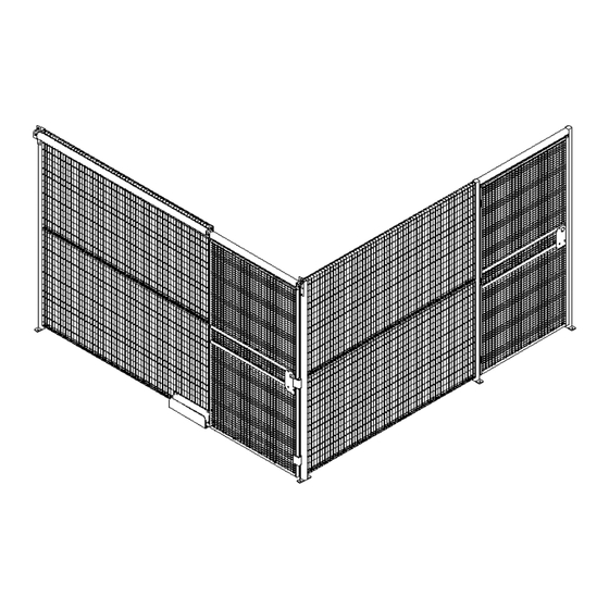
- Page 7 BEDFORD PARK, IL. 60638 Fax: (708) 325-0450 Step 1: Setting up for installation. Plan the layout of the Qwik-Fence® Perimeter Mark Every Post Location Mark Every Door Location To begin installation at a wall or corner. (Fig. 2-1) See Wall Kit Instructions Step 2.
- Page 8 Using the provided Carriage Bolt (F2), Hex Nut (F3), Washer (F4) secure the two panels together equally spaced for (three) 3 locations of bolts. Refer to Figure (5-1) for reference. Spaced equally through out the Panel (M1) span. Some cutting may be required See (Step 7). Fig. 5‐1 FGI-011_Rev.D 08/10/2015 Qwik-Fence Installation Instructions...
- Page 9 Using the provided TEK Screws (F1) secure the capping channel (M3) to the post (M2) using the hole in the capping channel (M3) as a pilot hole. Refer to Figure (10-1) for reference. Fig. 10‐1 FGI-011_Rev.D 08/10/2015 Qwik-Fence Installation Instructions...
- Page 10 Hinge Door Assembly Qwik-Fence ® Toll Free: (800) 622-2214 5858 W. 73 Phone: (708) 325-0400 BEDFORD PARK, IL. 60638 Fax: (708) 325-0450 Fig. 8‐1 FGI-011_Rev.D 08/10/2015 Qwik-Fence Installation Instructions...
- Page 11 If your door swings IN please refer to (Step 8F). If your door swings OUT please refer to (Step 8D). Fig. 8B‐1 Swing In Swing Out Swing Out Swing In Lock Right Lock Left Lock Right Lock Left FGI-011_Rev.D 08/10/2015 Qwik-Fence Installation Instructions...
- Page 12 AFTER you have Installed the Door as shown in Figure 8F-1 Receiver Bar Attach only at the top and the bottom, DO NOT screw in all the way. Place the Receiver Bar (D1) on top of Stop Angle (D3), line up the rectangular opening with the lock on the door and a ach using provided TEK Self Tapping Screws (F1) into the pre‐drilled holes. Use Figures (8F‐1) and (8E‐1) for reference. (A er ensuring that all assembly parts fit ghten the screws). Fig. 8F‐1 Lock Post FGI-011_Rev.D 08/10/2015 Qwik-Fence Installation Instructions...
- Page 13 Slide Door Assembly Qwik-Fence ® Toll Free: (800) 622-2214 5858 W. 73 Phone: (708) 325-0400 BEDFORD PARK, IL. 60638 Fax: (708) 325-0450 FGI-011_Rev.D 08/10/2015 Qwik-Fence Installation Instructions...
- Page 14 Assemble Slide Door Bracket (B4) and Slide Door Mounting Strip (B5) with an (F10), (F7) and (F3) as shown in Figure (9A-1). Please note that Mounting Strip (B5) has uneven placed holes make sure to attach the Bracket (B4) to the farthest hole. Fig. 9A‐1 FGI-011_Rev.D 08/10/2015 Qwik-Fence Installation Instructions...
- Page 15 (B5). Instead Measure 96” from the ground to the bo om of the Slide Door Bracket (B4) and using a TEK screw (F1) and (F4) washer a ach directly to post. Step 9D: Slide Door Assembly. Take the Assembled door (Step 9C) and insert the trolleys into the Slide Door Track (D6). See Figure 9D‐1 for reference. Slide the door all the way through. Make sure that that door moves freely with in the Slide Door Track (D6). Make sure there is a 2” clearance between the bo om of the door and the floor. If there is not adjust the trolleys un l there is. Fig. 9C‐2 Fig. 9C‐1 Please note that when inser ng the door assembly the front of the door should go in first and that the lock should be facing towards the direc ons that is specified in the Plan Drawings either provided by Folding Guard® or Your Company’s Representa ve. A er Inser ng the Door, please insert the Stop Bolt (F12) into the free hole in the Slide Door Fig. 9D‐1 Track Assembly on the back end of the door, and Tighten with Nut (F3). This will prevent the door from sliding out of the Slide Door Track (D6). CAUTION: Door Stop Bolt must be installed in order to prevent the door from exi ng the track. FGI-011_Rev.D 08/10/2015 Qwik-Fence Installation Instructions...
- Page 16 If a aching the Bo om guide to the wire mesh assemble the two halves of the Bo om Guide Fig. 9F‐1 (B6) and secure together with a Carriage Bolt (F2), Washer (F4) and a Nut (F3), as shown in Fig. 9F‐2 Figure 9F‐3. Step 9G: Bo om Guide Installa on. If a aching to the floor – place the bo om guide in such a ma er that when the door is closed the Door Guide (B8) is s ll inside the Bo om Guide Bracket (B6). Make sure that the door slides easily inside the floor bracket (B6) and there is no interference. Then a ach to the floor via concrete anchors. Fig. 9F‐3 If a aching to the wire mesh ‐ place the bo om guide in such a ma er that when the door is closed the Door Guide (B7) is s ll inside the Bo om Guide Bracket (B6). Make sure that the door slides easily inside the floor bracket (B6) and there is no interference. Then using the provided Bo om Guide A achment (B7). Fig. 9G‐1 Secure both via provided Carriage Bolt (F2), Washer (F4) and Nut (F3), as shown in Figure (9G‐1). FGI-011_Rev.D 08/10/2015 Qwik-Fence Installation Instructions...
- Page 17 When attaching to a roof support bracket please follow the directions in (Step 3) for attaching to a post. When attaching to another Ceiling panel please refer to (Step 5) for attaching to another panel. FGI-011_Rev.D 08/10/2015 Qwik-Fence Installation Instructions...
Need help?
Do you have a question about the Qwik-Fence and is the answer not in the manual?
Questions and answers