
Summary of Contents for Cleaver-Brooks CB780
- Page 1 $25.00 Cleaver-Brooks CB780/CB784 Operation and Maintenance Manual 750-166 DIVISION OF AQUA-CHEM, INC.
- Page 2 Cleaver-Brooks equipment is designed and engineered to give long life and excellent service on the job. The electrical and mechanical devices supplied as part of the unit were chosen because of their known ability to perform; however, proper operating techniques and maintenance procedures must be followed at all times.
- Page 3 Cleaver-Brooks CB780/CB784 Operation and Maintenance Manual © Aqua-Chem, Inc., 1995 Please direct purchase orders for replacement manuals to your local Cleaver-Brooks authorized representative Manual Part Number 750-166 6/95 Rev 10/95 Printed in U.S.A.
- Page 4 CONTENTS Section 1 – Installation and Operating Instructions Section 2 – System Annunciation Diagnostics and Troubleshooting...
-
Page 5: Table Of Contents
The CB780 consists of a Relay Module and Keyboard Display Module. The CB784 consists of the Relay Module only. The Keyboard Display Module is optional with the CB784. Sub- base, Amplifier, and Purge Card are required to complete the system. -
Page 6: Specifications
120 Vac, 0.5A. The CB780/CB784 must have an earth ground providing a connection between the subbase and the control panel or the equipment. The earth ground wire must be capable of conducting the current to blow the 20A fuse (or breaker) in event of an internal short circuit. - Page 7 The MFEP will be determined by which terminal is used, see Figs. 7 and 18. The operating sequence of the CB780 and CB784 Relay Modules are identical. The only difference between the Relay Modules is that the Keyboard Display Module is standard with the CB780 and optional with the CB784.
- Page 8 NOTE: The CB780 and CB784 are identical except for the Keyboard Display Module which is standard with the CB780 and optional with the CB784. Fig. 1—Mounting dimensions of CB780/CB784 Relay Module and 833-2725 Subbase, in inches (mm) BURNER CONTROL SCROLL...
- Page 9 COLLAR, 3/4-14 NPSM 5/32 (4) 5/15 INTERNAL THREADS M1982A 3-7/8 (99) M7405 (12) 817-1742 (11) 833-2727 (Standard with CB780, optional with CB784) Fig. 3—Ultraviolet Self-Check detector. MOUNTING FLANGE 3/4–14 NPT 7-7/32 (183) 5-1/8 (130) 3-3/4 (95) 3-7/16 (87) 1/2–14 NPSM...
- Page 10 CB780/CB784 PRINCIPAL TECHNICAL FEATURES Principal Technical Features The CB780/CB784 provides all customary flame safe- i. Internal system fault. guard functions while providing significant advancements in j. Purge card is removed. the areas of safety, annunciation and system diagnostics. k. Purge card is bad.
-
Page 11: Safety Provisions
PREPURGE, the CB780/CB784 will lockout on safety shut- include a flame signal check during STANDBY, a preigni- down. The CB780/CB784 must react to input changes but tion interlock check, an interlock check, and a safety critical avoid the occurrence of nuisance shutdown events. Signal load check. - Page 12 Faults associated within the flame detection subsystem, time after the first 40 seconds of STANDBY, a safety shut- CB780/CB784 or plug-in Purge Card, are isolated and re- down will occur and be annunciated. A shutter-check ampli- ported by the Keyboard Display Module. See the Diagnos-...
-
Page 13: Installation
CAUTION VIBRATION 1. Disconnect the power supply before beginning Do not install the CB780/CB784 where it could be sub- installation to prevent electrical shock, equip- jected to vibration in excess of 0.5G continuous maximum ment and control damage. More than one power vibration. - Page 14 CB780/CB784 INSTALLATION Fig. 6—Internal block diagram of the CB780/CB784 (see Figs.7,8,9, or 10 for detailed wiring instructions). (HOT) 120 Vac PLUG-IN PURGE CONFIGURATION TIMER CARD JUMPERS TEST FLAME SIGNAL JACK RUN/TEST SWITCH PLUG-IN MICROCOMPUTER FLAME AMPLIFIER TEST RESET PUSHBUTTON RELAY...
-
Page 15: Wiring
120 ohm (1/4 watt breaker) in event of an internal short circuit. The minimum) resistor termination across terminals CB780/CB784 needs a low impedance ground 1 and 2 of the electrical connectors, for connec- connection to the equipment frame which, in tions over 100 feet, see Fig. - Page 16 4. Follow directions in flame detector Instructions. 8. Make sure loads do not exceed the terminal ratings. b. Control Bus: Refer to the label on the CB780/CB784 or to the ratings in 1. Do not run high voltage ignition transformer Specifications; see Table 1.
- Page 17 CB780/CB784 WIRING FIG. 7—WIRING CB780/CB784 SERIES 90 FIRING RATE SERIES 90 833-2725 MOTOR CONTROLLER HIGH FIRE COMMON LOW FIRE 120V ALARM MODULATE (L1) BURNER MOTOR (BLOWER) BURNER CONTROLLER/LIMITS LOCKOUT INTERLOCKS LOW FIRE (INC. AIR FLOW SWITCH) START SWITCH 10 SEC. INTERRUPTED...
- Page 18 2 REMOTE RESET MUST BE MOUNTED WITHIN SIGHT OF THE BOILER CONTROL PANEL. Fig. 10—Wiring the Control Bus with remote Keyboard Display Module. 833-2729 DATA CONTROLBUS MODULE™ (MOUNTED ON CB 780/CB 784) 833-2729 CONTROL BOX (MOUNTED ON CB780/CB784) MOMENTARY PUSH BUTTON SWITCH 120 OHM...
-
Page 19: Assembly
Keyboard Display Module, or Control Bus . 4. Mount the CB780/CB784 by aligning the four L shaped corner guides and knife blade terminals with the bifurcated MOUNTING KEYBOARD DISPLAY MODULE... - Page 20 More than one disconnect may be involved. 2. Align the amplifier circuit board edge connector with the keyed receptacle on the CB780/CB784. Verify the am- plifier nameplate faces away from the Relay Module, see Fig. 16.
- Page 21 CB780/CB784 ASSEMBLY Fig. 15—Remote mounting of Keyboard Fig.17—Flame detector wiring. Display Module. INFRARED (817-1742) ULTRAVIOLET (817-1743) BLUE WHITE SOLID STATE SELF-CHECKING ULTRAVIOLET (817-1121) Fig. 16—Flame signal amplifier mounting. BLUE YELLOW WHITE WHITE BLACK BLACK FLAME DETECTOR LEADS ARE COLOR CODED. THE BLUE LEAD MUST BE CONNECTED TO THE F TERMINAL AND THE WHITE MUST BE CONNECTED TO THE G TERMINAL.
-
Page 22: Operation
MFEP. After the Ignition Trials, and with the pres- tored circuits must be in the correct state for the CB780/ ence of flame, the main fuel valve, terminal 9, is CB784 to continue into the PREPURGE sequence. - Page 23 9 and 21, are de-energized and the firing rate motor is 3. After the fifteen second POSTPURGE period is com- commanded to the low fire position to begin the POSTPURGE pleted, the CB780/CB784 reenters STANDBY. period. Fig. 18—CB780/CB784 sequence.
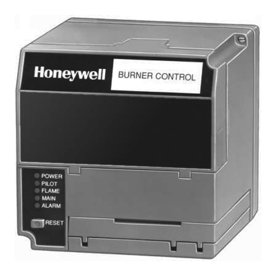
- Page 24 CB780/CB784 OPERATION message will replace a selectable message to support the available. The CB780/CB784 LEDs provide positive visual sequence status information. It will also replace a selectable indication of the program sequence: POWER, PILOT, message after 60 seconds if it or a lockout message is FLAME, MAIN and ALARM.
- Page 25 Additional sequence status information when an Expanded Annunciator is connected to the relay module, also see Additioanl sequence status information when an Expanded Annunciator is connected to the relay module. Also see CB780/CB784 Operating and Maintenance Manual, Manual Number 750-166. CB 780/CB 784 System Annunciation Diagnostics and Troubleshooting, Bulletin Number CB-7803.
- Page 26 CB780/CB784 OPERATION ↔ Fig. 21 ( )—Change-Level pushbutton function. SAVE SAVE M7402 Fig. 22—MODE pushbutton function. SAVE SAVE M7403 4. SAVE function; see Fig. 23. Fig. 23—SAVE function. The SAVE function enables users to identify the select- able message they want to view upon power restoration. The second line selectable message will be restored to the most recently saved selection when power returns.
- Page 27 CB780/CB784 OPERATION TABLE 5—SELECTABLE MESSAGES. Selectable Message Display Value First Line (Second Line) (Second Line) Message Flame Signal n.nV Total Cycles nnnnn Total Hours nnnnn Fault History↔ nnnnn < ↓H1 Fault Cycle nnnnn < ↓H1 Fault Hours ↓H1 Fault Code nnn <...
- Page 28 ↓EA Software Revision (SW Rev.) nnnn< Expanded Annunciator Diagnostic Current Status Messages can be reviewed in CB780/CB784 Operating and Maintenance Manual, Manual Number 750-166. RUN/TEST SWITCH FUNCTIONS to be made. This activates a fifteen second flameout timer The Run/Test Switch is located on the top side of the that permits pilot flame adjustment without nuisance safety CB780/CB784;...
-
Page 29: Static Checkout
Internal surge protectors will break down and place all damaged or incorrectly sized wires. conduct a current. This could cause the CB780/CB784 to 9. Replace faulty controllers, limits, interlocks, actuators, fail the dielectric test or possibly destroy the internal valves, transformers, motors and other devices as required. - Page 30 CB780/CB784 STATIC CHECKOUT TABLE 8—STATIC CHECKOUT. Test Test Volt- If Operation is Abnormal, Check the Jumpers meter Normal Operation Items Listed Below WARNING Make sure all manual fuel shutoff valves are closed. IMPORTANT: Low fuel pressure limits, if used, could be open. Bypass them with jumpers for the remaining Static Tests (if required).
-
Page 31: Checkout
Do not allow fuel to accumulate in the combus- time on the display. Refer to the Troubleshooting sec- tion chamber. If fuel is allowed to enter the tion of the CB780/CB784 Operation and Maintenance chamber for longer than a few seconds without Manual, Manual Number 750-166. - Page 32 CB780/CB784 CHECKOUT • Flame signal with hot combustion chamber—all 7. Power is connected to the system disconnect switch, installations. (master switch). • Safety shutdown tests—all installations. 8. Lockout is reset (push in reset button) only if the Relay See Figs. 1 and 2 for location of component parts and Module is powered;...
- Page 33 11. Recycle the system to recheck the lightoff and pilot call for heat by raising the set point of the operating control- flame signal. ler; see Fig. 19 or CB780/CB784 sequence. The program 12. Smoothly open the manual fuel shutoff valve(s) and should start the ten second INITIATE sequence.
- Page 34 Fig.18 for CB780/CB784 sequencing. The program modulating. Any pulsating or unsteady readings will require sequence should start the ten second INITIATE sequence.
- Page 35 FLAME LED goes out. Note the pressure at the until a smooth main flame is accomplished. CB780/CB784 flame relay dropout point. The pilot is at the 14. Reposition the flame scanner sight tube or use orifices minimum turndown position. Immediately turn up the pilot until the pilot flame signal voltage is in the range of 1.25 to...
- Page 36 CB780/CB784 CHECKOUT HOT REFRACTORY SATURATION TEST aware that it must also properly sight the flame. For an infrared (ALL INFRARED DETECTORS) detector, try lengthening the sight pipe or decreasing the pipe Test to make certain that radiation from hot refractory size (diameter).
- Page 37 VFD. Fault code 28 will be displayed four or ten IMPORTANT: seconds (depending on the jumper configuration 1. If the CB780/CB784 fails to shut down on any of these selection for PFEP) after the pilot valve(s) is tests, take corrective action; refer to CB780/CB784 energized to denote the fault.
-
Page 38: Troubleshooting
Display Module or Control Bus. A power-up reset will messages and fault codes. In addition, Diagnostic Informa- cause an electrical reset of the CB780/CB784, but will not tion and History Data are available to assist in troubleshoot- reset a lockout condition. - Page 39 CB780/CB784 TROUBLESHOOTING TABLE 10—HOLD AND FAULT MESSAGE SUMMARY. Fault Number Annunciation Message Fault 1 *No Purge Card* Fault 2 *AC Frequen/Noise* Fault 3 *AC Line Dropout* Fault 4 *AC Frequency* Fault 5 *Low Line Voltage* Fault 6 *Purge Card Error*...
- Page 40 CB780/CB784 TROUBLESHOOTING Fig. 28—Flush mounting of a Keyboard Display Module template. 1/8 DIA. (2) M5082A...
- Page 41 Keyboard Display Module (standard aid the service mechanic in obtaining information when on CB780, optional on CB784) 2 row by 20 column Vacuum troubleshooting the system, see Tables 1, 2, 3 and 4. Infor- Fluorescent Display (VFD). The CB780/CB784 provides...
- Page 42 SERVICE NOTE: Reset the CB780/CB784 by pressing The CB780/CB784 retains historical information for the reset button on the CB780/CB784, or pressing a re- the six most recent lockouts. Each of the six lockout records mote reset pushbutton wired through the Keyboard Dis- retain the cycle when the fault occurred, the hour of opera- play Module or Control Bus.
- Page 43 TABLE 1—SEQUENCE AND STATUS HOLD MESSAGES FOR ALL CB780/CB784 CONTROLS (Continued). Sequence Burner Control Status STANDBY HOLD: T7 The KDM indicates the burner status, STANDBY, and that the Lockout Interlock is (Lockout Interlock) closed. If a demand is present for burner operation, the burner sequence will not advance to PREPURGE until the Lockout Interlocks prove open.
- Page 44 TABLE 1—SEQUENCE AND STATUS HOLD MESSAGES FOR ALL CB780/CB784 CONTROLS (Continued). Sequence Burner Control Status RESET/ALARM TEST The KDM indicates the burner status, RESET/ALARM TEST. This display indicates that the reset button is pressed. If it is held for more than four seconds, the alarm output is energized.
- Page 45 TABLE 3—SELECTABLE MESSAGES (see CB780/CB784 Relay Module, Manual Part Number 750-166). Selectable Possible States/Range Message/Display Description (Terminals) Comments Flame Signal Flame signal strength. 0 - 5.0 Vdc Flame Flame relay pull-in and drop- Amp (+ and - (Com)) out value 1.25 Vdc.
- Page 46 TABLE 3—SELECTABLE MESSAGES (Continued). Selectable Possible States/Range Message/Display Description (Terminals) Comments LowFire Sw T18 Low Fire Switch. 1 or 0 Indicates if input is on or off, energized or deenergized. HighFire Sw High Fire Switch. 1 or 0 Indicates if input is on or off, energized or deenergized.
- Page 47 LOCKOUT MESSAGES (TABLE 4) 3. STATE 3, see Fig. 3: Display of the third state mes- When the CB780/CB784 is locked out, it displays a sage lasts three seconds. It is a replica of the burner status as repeating cycle of messages (in English text); see Table 4.
- Page 48 TABLE 4—FAULT MESSAGE AND RECOMMENDED TROUBLESHOOTING. Fault Code System Failure Recommended Troubleshooting Fault 01 No card is plugged into the 1. Assure the purge card is seated properly. *No Purge Card* purge card slot. 2. Inspect the purge card and the connector on the relay module for damage or contaminants.
- Page 49 TABLE 4—FAULT MESSAGE AND RECOMMENDED TROUBLESHOOTING (Continued). Fault Code System Failure Recommended Troubleshooting Fault 08 Flame sensed when checked for 1. Check wiring; correct any errors. *Flame Amp/Shutr* shutter-check or ampli-check 2. Assure that the flame detector and flame versions. amplifier are compatible.
- Page 50 TABLE 4—FAULT MESSAGE AND RECOMMENDED TROUBLESHOOTING (Continued). Fault Code System Failure Recommended Troubleshooting Fault 14 High fire interlock switch failure 1. Check wiring; correct any errors. *High Fire Sw.* to close during prepurge. 2. Reset and sequence the CB 780/CB 784. 3.
- Page 51 TABLE 4—FAULT MESSAGE AND RECOMMENDED TROUBLESHOOTING (Continued). Fault Code System Failure Recommended Troubleshooting Fault 18 Flame sensed when shutter open 1. Check that flame is not present in the combustion *Flame Detected* and no flame is expected during chamber. Correct any errors. Prepurge.
- Page 52 TABLE 4—FAULT MESSAGE AND RECOMMENDED TROUBLESHOOTING (Continued). Fault Code System Failure Recommended Troubleshooting Fault 24 The Flame Interlock (relay 1. Reset and sequence the CB 780/CB 784. *Call Service* module) was on when it should 2. If fault persists, replace the relay module. have been off.
- Page 53 TABLE 4—FAULT MESSAGE AND RECOMMENDED TROUBLESHOOTING (Continued). Fault Code System Failure Recommended Troubleshooting Fault 33 Preignition Interlock fault. 1. Check wiring; correct any errors. *Preignition ILK* 2. Inspect the Preignition Interlock switches and assure proper funcitoning. 3. Check fuel valve operation. Valve must close within five seconds.
- Page 54 TABLE 4—FAULT MESSAGE AND RECOMMENDED TROUBLESHOOTING (Continued). Fault Code System Failure Recommended Troubleshooting Fault 44 V2S valve terminal, used as a 1. Warning! Remove system power; turn off fuel *Pilot Valve 2 On* pilot, was on when it should be supply.
- Page 55 TABLE 4—FAULT MESSAGE AND RECOMMENDED TROUBLESHOOTING (Continued). Fault Code System Failure Recommended Troubleshooting Fault 67 L1 and L2 miswired/exchanged. 1. Check L1 and L2 for proper line phasing. *AC Phase* Fault 105 Relay Module self-test failure. 1. Reset and sequence the CB 780/CB 784. *Call Service* 2.
- Page 56 TABLE 4—FAULT MESSAGE AND RECOMMENDED TROUBLESHOOTING (Continued). Fault Code System Failure Recommended Troubleshooting Fault 119 Relay Module self-test failure. 1. Reset and sequence the CB 780/CB 784. *Call Service* 2. If fault persists, replace the relay module. Fault 120 Relay Module self-test failure. 1.
- Page 57 TABLE 5—CB783 EXPANDED ANNUNCIATOR HOLD CODES. Annunciation Message Symbol System Holds BURNER OFF: T6 Burner switch is open. (Burner Switch) STANDBY HOLD: T6 Auxiliary limit #1 is open. (Aux. Limit #1) STANDBY HOLD: T6 Auxiliary limit #2 is open. (Aux. Limit #2) STANDBY HOLD: T6 Open low water cutoff.
- Page 58 TABLE 6—CB783 EXPANDED ANNUNCIATOR FAULT CODES. Annunciation Message Symbol System Faults LOCKOUT nna Auxiliary limit #1 is open. *Aux. Limit #1* LOCKOUT nnb Auxiliary limit #2 is open. *Aux. Limit #2* LOCKOUT nnc Open low water cutoff. *LWCO* LOCKOUT nnd High limit (pressure or temperature) is exceeded.
- Page 59 CB783 EXPANDED ANNUNCIATOR DIAGNOS- TABLE 7—CB783 EXPANDED ANNUNCIATOR TIC CURRENT STATUS MESSAGES (TABLE 7) DIAGNOSTIC CURRENT STATUS MESSAGES. These messages are used to provide information from the Display Description CB783 Expanded Annunciator to the Keyboard Display Module in the EA Diagnostic section under Current Status; Burner Sw.
- Page 60 NOTES 2-20 750-166...
- Page 61 Tecnnology Proven Worldwide...
Need help?
Do you have a question about the CB780 and is the answer not in the manual?
Questions and answers