Table of Contents
Advertisement
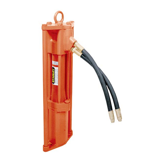
PD45
HYDRAULIC
POST DRIVER
WARNING
S
, O
M
AFETY
PERATION AND
AINTENANCE
USER'S MANUAL
Stanley Hydraulic Tools
3810 SE Naef Road
Milwaukie OR 97267-5698
© Stanley Hydraulic Tools 2005
503-659-5660
OPS/MAINT USA / CE
FAX 503-652-1780
Printed in U.S.A.
www.stanley-hydraulic-tools.com
59010 9/2005 ver 3
Advertisement
Table of Contents

Subscribe to Our Youtube Channel
Related Manuals for Stanley PD45


Summary of Contents for Stanley PD45
- Page 1 HYDRAULIC POST DRIVER WARNING AFETY PERATION AND AINTENANCE USER’S MANUAL Stanley Hydraulic Tools 3810 SE Naef Road Milwaukie OR 97267-5698 © Stanley Hydraulic Tools 2005 503-659-5660 OPS/MAINT USA / CE FAX 503-652-1780 Printed in U.S.A. www.stanley-hydraulic-tools.com 59010 9/2005 ver 3...
-
Page 3: Table Of Contents
REPAIRS AND / OR SERVICE TO THIS TOOL MUST ONLY BE DONE BY AN AUTHORIZED AND CERTIFIED DEALER. For the nearest authorized and certifi ed dealer, call Stanley Hydraulic Tools at the number listed on the back of this manual and ask for a Customer Service Representative. -
Page 4: Safety Symbols
SAFETY SYMBOLS Safety symbols and signal words, as shown below, are used to emphasize all operator, maintenance and repair actions which, if not strictly followed, could result in a life-threatening situation, bodily injury or damage to equip- ment. This is the safety alert symbol. It is used to alert you to potential personal injury hazards. -
Page 5: Safety Precautions
If so, place the added precautions in the space provided in this manual. The models PD45 Hydraulic Post Driver will provide safe and dependable service if operated in accordance with the instructions given in this manual. Read and under- stand this manual and any stickers and tags attached to the tool and hoses before operation. - Page 6 • Do not exceed the rated limits of the tool or use the tool for applications beyond its design capacity. • Always keep critical tool markings, such as labels and warning stickers legible. • Always replace parts with replacement parts recommended by Stanley Hydraulic Tools. • Check fastener tightness often and before each use daily.
-
Page 7: Tool Stickers & Tags
USE ONLY PARTS AND REPAIR USE ONLY PARTS AND REPAIR instructions listed on this PROCEDURES APPROVED BY PROCEDURES APPROVED BY STANLEY AND DESCRIBED IN THE STANLEY AND DESCRIBED IN THE tag before removal. We OPERATION MANUAL. OPERATION MANUAL. suggest you retain this tag... -
Page 8: Hydraulic Hose Requirements
HOSE SAFETY TAGS To help ensure your safety, the following DANGER tags are attached to all hose purchased from Stanley Hydrau- lic Tools. DO NOT REMOVE THESE TAGS. -
Page 9: Htma Requirements
HTMA REQUIREMENTS TOOL CATEGORY HYDRAULIC SYSTEM REQUIREMENTS TYPE 1 TYPE II TYPE III TYPE RR FLOW RATE 4-6 gpm 7-9 gpm 11-13 gpm 9-10.5 gpm (15-23 lpm) (26-34 lpm) (42-49 lpm) (34-40 lpm) TOOL OPERATING PRESSURE 2000 psi 2000 psi 2000 psi 2000 psi (at the power supply outlet) -
Page 10: Operation
OPERATION PRE-OPERATION PROCEDURES TOOL OPERATION 1. Observe all safety precautions. CHECK THE POWER SOURCE 2. Install the appropriate adapter as required. 1.Using a calibrated fl owmeter and pressure guage, check that the hydraulic power source develops a fl ow of 7-9 3. -
Page 11: Charging The Accumulator
A. Remove the charging valve plug from the post driver. Note: B. Holding the chuck end of Stanley tester (Part Number It may be necessary to set the regulator at 650 to 700 02835), turn the gauge fully counter-clockwise to ensure psi/45-48 bar to overcome any pressure drop through the stem inside the chuck is completely retracted. -
Page 12: Equipment Protection & Care
fl ow. This can cause damage to internal seals. • Always replace hoses, couplings and other parts with replacement parts recommended by Stanley Hydraulic Tools. Supply hoses must have a minimum working pressure rating of 2500 psi/172 bar. -
Page 13: Troubleshooting
TROUBLESHOOTING If symptoms of poor performance develop, the following chart can be used as a guide to correct the problem. When diagnosing faults in operation of the tool, always make sure the hydraulic power source is supplying the correct hydraulic fl ow and pressure as listed in the table. Use a fl owmeter know to be accurate. check the fl ow with the hydraulic fl... -
Page 14: Specifications
SPECIFICATIONS Weight (Standard) ............................65 lbs / 29.5 kg Weight (Extended anvil) ............................ 71 lbs / 32 kg. Pressure Range ............................2000 psi / 140 bar Flow Range ..............................7-9 gpm / 26-34 lmp Optimum Flow ..............................8 gpm / 30 lpm HTMA Class II ............................ -
Page 15: Pd45 Remote Valve Parts Illustration
PD45131 PARTS ILLUSTRATION... -
Page 16: Pd45 Remote Valve Parts List
PD45131 PARTS LIST Item Item Part No. Description Part No. Description 15197 Name Tag 15190 Top Plate 11588 Accumulator Valve Block Adapter, 1/2 inch SAE to 3/8 00936 NPT Male 04374 Locknut 5/8-18 19693 Danger Sticker 00293 O-ring 13568 Back Up Ring 15188 Valve Spool 13567... -
Page 17: Pd45132 Parts Illustration
PD45132 PARTS ILLUSTRATION... -
Page 18: Pd45132 Parts List
PD45132 PARTS LIST Item Item Part No. Qty. Description Part No. Qty. Description 07493 O-Ring Plug-Male 11588 Accumulator Valve Block 20499 Charge Valve 20396 Valve Top Plate 20387 Plunger 20392 Trigger Assy 12100 Steel Ball 3/8 Dia. G 00038 Nut 1/4-20 Plain 00899 HHCS 1/4-20 UNC x ½... -
Page 19: Warranty
fi rst retail purchaser, or for a period of 2 years from the shipping date from Stanley, whichever period expires fi rst, to be free of defects in material and/or workmanship at the time of delivery, and will, at its option, repair or replace any tool or part of a tool, or new part, which is found upon examination by a Stanley authorized service outlet or by Stanley’s factory in Milwaukie, Oregon to be DEFECTIVE IN MATERIAL AND/OR WORKMANSHIP. - Page 20 Stanley Hydraulic Tools 3810 SE Naef Road Milwaukie, Oregon 503-659-5660 / Fax 503-652-1780 www.stanley-hydraulic-tools.com...
Need help?
Do you have a question about the PD45 and is the answer not in the manual?
Questions and answers