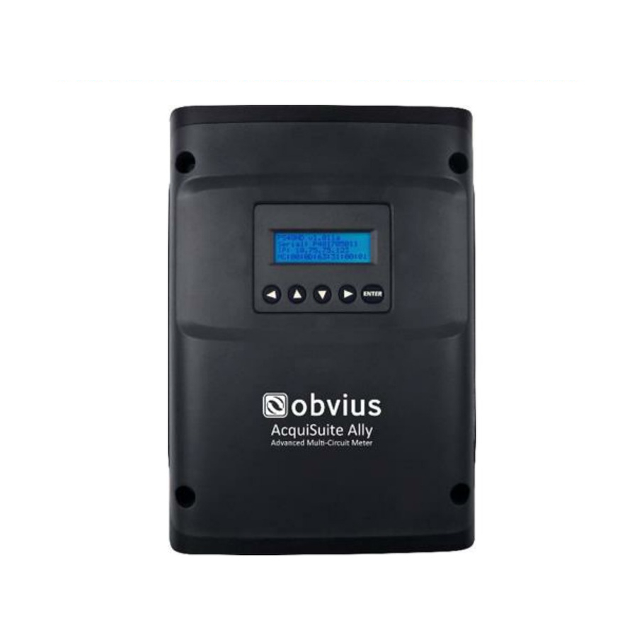
Summary of Contents for Obvius AcquiSuite Ally 12
- Page 1 AcquiSuite™ Ally 12 & 48 Advanced Multi-Circuit Meter Install Guide Revision C (12/18)
- Page 2 Revision C (12/18) DANGER HAZARD OF ELECTRIC SHOCK, EXPLOSION, OR ARC FLASH • Turn off all power supplying equipment before working on or inside the equipment. • Follow safe electrical work practices. See NFPA 70E in the USA, or applicable local codes. •...
-
Page 3: Technical Specifications
Revision C (12/18) Technical Specifications Specification Description Single Phase, Split Phase, Three Phase-Four Wire (WYE), Three Phase-Three Wire Service Types (Delta) 90-346 Volts AC Line-to-Neutral, 600V Line-to-Line, CAT III. Voltage Channels Two independent voltage reference inputs 48 channels, 0.525 VAC max, 333 mV CTs, 0-4,000+Amps depending on current Current Channels transducer 150% of current transducer rating (mV CTs) to maintain accuracy. - Page 4 (L) 24.7cm x (W) 25.2cm x (H) 8.0 cm (9.8” x 10” x 3.1”) (no enclosure version) (L) 21.6cm x (W) 21.6.0cm x (H) 6.4 cm (8.5” x 8.5” x 2.5”) PCBA Dimensions Obvius Ally Configuration Console™ Minimum System Requirements Windows® 7. Windows® 8, Windows® 10 Operating System...
- Page 5 Revision C (12/18) Mechanical Specifications & Mounting Series AMC48 - Enclosure Series AMC12 - Enclosure...
- Page 6 Revision C (12/18) Series AMC48 – Enclosure Drill Pattern Series AMC12 – Enclosure Drill Pattern...
- Page 7 Revision C (12/18) Series AMC48 – Mounting Plate Template...
- Page 8 Revision C (12/18) The following section illustrates the 12 channel model. The mounting components are slightly different, but follow the same procedure. STEP 1) Remove top cover screws (4x) and high voltage cover screws (2x) – provided STEP 2) Locate, mark, and drill wall mounting points (2x–6x—customer supplied) The plastic enclosure itself can be used as a template for marking the drill locations on the wall.
- Page 9 Revision C (12/18) STEP 3) Mount conduit fittings, conduits, and blanking plugs STEP 4) Connect voltage leads...
-
Page 10: Connecting Voltage
Revision C (12/18) STEP 5) Attach high voltage cover IP30 TOUCH SAFE (with internal cover installed) STEP 6) Connect CT and Communications Wiring Connecting Voltage Connect the voltage leads (L1, L2, L3, and N, as necessary) to the meter through a dedicated disconnect or circuit breaker. - Page 11 Revision C (12/18) Wiring the AcquiSuite™ Ally Meter in a 3-wire, Split ɸ Service Panel High voltage MAY BE PRESENT. Risk of electric shock. Life threatening voltages may be present. Qualified personnel only. Connect the 3-Wire, 1 Phase used Neutral wire to On MAINS V INPUT 1 (N) on L1-N, L2-N...
- Page 12 Revision C (12/18) Wiring the AcquiSuite™ Ally Meter in a 4-wire, 3 ɸ Service Panel 3 Wire, 3 ɸ used On MAINS L1-N, L2-N, L3-N Connect the (Rogowski Coils Shown) Neutral wire or Ground wire to V INPUT 1 (N) on the meter Single Phase Meter Power...
- Page 13 Revision C (12/18) Wiring the CTs to the AcquiSuite™ Ally Meter The image below is the counterpart to the service panel illustration and indicates how to connect CTs to the input terminals on the AcquiSuite™ Ally, for each service type. For service types that are not specifically listed, it is recommended to choose “single phase”...
- Page 14 Revision C (12/18)
- Page 15 Revision C (12/18) Communication Verification Verification includes confirmation of BOTH the physical interface settings (Serial or Ethernet) and the protocol (Modbus or BACnet) settings. The LCD User interface can be used to quickly confirm the settings required for each combination of interface and protocol. The interface is intuitive and groups together commonly associated registers.
-
Page 16: Pulse Inputs
50mS in both the logic low and high state allowing for a maximum input frequency of 10 Pulse scaling, resetting and accumulated values are accessed through registers and are “system” in scope. Refer to the register list, Obvius Ally Configuration Console, or videos for more information. >50 mec >50 mec...


Need help?
Do you have a question about the AcquiSuite Ally 12 and is the answer not in the manual?
Questions and answers