Advertisement
Quick Links
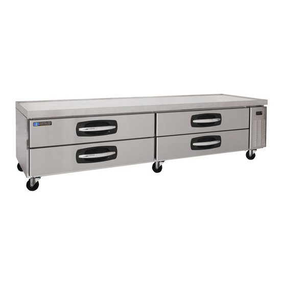
CHEF BASE CABINETS
Installation, Operation and Maintenance Instructions
INSPECTION
When the equipment is received, all items should be carefully checked against the Bill
of Lading to ensure all crates and cartons have been received. Do not sign the freight
bill clear until the freight has been properly inspected for damage. All units should be
inspected for damage including concealed damage by uncrating immediately. If any
damage is found, it should be reported to the carrier at once, noted on the Bill of Lading
and a claim should be filed with the carrier. This equipment has been inspected and
tested in the manufacturing facility and has been crated in accordance with
transportation rules and guidelines. The manufacturer is not responsible for freight loss
or damages.
INSTALLATION
The exterior top of the cabinet has been protected by a plastic covering. Peel this
protective covering before installation. After removing the covering, clean the interior
and exterior surfaces of the unit with soap and water and a rinse with clean water. Do
not use chlorinated cleaners on the surfaces as they can cause corrosion.
The refrigeration system located on the side of the unit requires free air access for
proper operation. Allow a minimum of seven inches between the back of the cabinet
and the wall. The equipment is designed to accept heat generating cooking equipment if
the equipment is properly installed with legs (supplied by the cooking equipment
manufacturer). A minimum clearance of 4 inches is required between the bottom of the
cooking equipment heating element and the cabinet top. Failure to provide adequate
clearance voids manufacturer warranty. Installation of a heat shield (supplied by others)
is recommended for optimum performance.
Confirm that the proposed electrical outlet has the correct voltage, frequency and
current carrying capacity for the requirements of the unit. This information is noted on
the data plate on the inside left wall of the unit. The unit should be isolated on a circuit.
Do not use an extension cord to get power to the unit. Improper electrical installations
will void the compressor warranty. To prevent shock and fire, be sure the unit is properly
grounded.
The temperature controller is located inside the refrigerated compartment in the back
right top corner. The default temperature is set at "normal". Adjust the temperature to fit
your needs. It is not recommended that the cabinet be run colder than +34°F.
1
05/15 Rev. H 147774
Advertisement

Related Manuals for Master Bilt CB36


Summary of Contents for Master Bilt CB36
- Page 1 CHEF BASE CABINETS Installation, Operation and Maintenance Instructions INSPECTION When the equipment is received, all items should be carefully checked against the Bill of Lading to ensure all crates and cartons have been received. Do not sign the freight bill clear until the freight has been properly inspected for damage. All units should be inspected for damage including concealed damage by uncrating immediately.
-
Page 2: Maintenance
CAUTION! DO NOT SIT OR STAND ON TOP OF THESE CABINETS AND DO NOT USE THE DRAWERS AS A STEP. SERIOUS INJURIES CAN OCCUR. Install casters per the following diagram. Note: Install casters with brakes to the front of the cabinet. MAINTENANCE General Cleaning Beginning with the initial installation, the interior surfaces of the cabinet should be... -
Page 3: Troubleshooting
TROUBLESHOOTING Problem Remedy · Check the power cord and make sure it is plugged in. Compressor will · Check the temperature controller. If it is in the “OFF” position, not start turn it clockwise to set a desired temperature. · Move the unit from direct sunlight. ·... -
Page 4: Specifications
SPECIFICATIONS * Includes 5 inches for casters. ** Above specifications are subject to change without prior notice for quality improvement. *** Relative humidity should be kept between 30% - 60%, maintaining a dew point of +50°F or less. 05/15 Rev. H 147774... - Page 5 05/15 Rev. H 147774...
- Page 6 ▣ Chef Base – Drawer Structure Small drawers Tray Frame Assy – small – ITEM 6 Supporter Pan – A – ITEM 32 Door Gasket – small – ITEM 13 Door Assembly- small – ITEM 10 Large drawers Tray Frame Assy – big – ITEM 5 Supporter Pan –...
- Page 7 ▣ Chef Base – Machine Room Disassembly ▣ Chef Base – Internal Structure EVAP. FAN GUARD Small – ITEM 35 EVAP. DUCT (3F) Large – ITEM 36 REAR COVER 1 Fan – ITEM 38 Large – ITEM 37 ITEM 34 2 Fan –...
- Page 8 ▣ Chef Base – Wiring Diagram [CB36, CB48, CB53, CB60, CB72] ▣ Chef Base – Wiring Diagram [CB84,CB96] 05/15 Rev. H 147774...