Table of Contents
Advertisement
Advertisement
Table of Contents
Troubleshooting

Summary of Contents for HEXMOTO Indverter V2
- Page 1 Indverter V2 User Manual HEXMOTO Controls Pvt.Ltd...
- Page 2 Indverter V2 Manual HEXMOTO Issue 03 Dated 11 November 2009 S/w Ver 12.4 Controls Pvt.Ltd...
- Page 3 Please read this user manual carefully before installation, operation, maintenance or inspection of the drive system. Hexmoto make Indverter V2 series drives are simple to configure and easy to operate. This manual is intended to provide sufficient information for installation and operation of the drive system.
-
Page 4: Table Of Contents
Indverter V2 Manual Table of Contents 1. Glossary of Terms Used 2. Safety Precautions 3. Inspection of the Module 4. Technical Specifications 5. Dimensional Details 6. Display and Keypad 7. Installation and Commissioning 8. List of Parameters 9. Description of Parameters and programming 10. -
Page 5: Glossary Of Terms Used
Indverter V2 Manual 1. GLOSSARY OF TERMS USED Drive Module Refers to Hexmoto make Indverter V2 series controller. Term is used in combination “Drive Module” or separately as “ Drive” or “Module” to indicate the Indverter V2 Controller Inverter Refers to Drive module... -
Page 6: Safety Precautions
Indverter V2 Manual 2. SAFETY PRECAUTIONS It is recommended that only authorized personnel be permitted to perform handling, maintenance and inspection of the drive module. In this manual, notes for safe operation are classified under “ WARNING” or “CAUTION” using... -
Page 7: Inspection Of The Module
Visual check of module parts such as display unit, cooling fan and mounting arrangements is necessary. Except for the Indverter V2 module and the User manual, all other items are optional and must be checked for list of ordered items. In case of Natural air-cooled modules, Cooling Fans are not mounted inside the module. - Page 8 SOURCE : AC 3Ph, 415V, -15%, +10%, 50/60 Hz. Rated current O/P : CURRENT A FREQ.: 1-400Hz of the Module SERIAL No. HEXMOTO CONTROLS PVT. LTD., MYSORE 570018 - INDIA WWW.HEXMOTO.COM Module Serial Number Selection Chart Type V2 2K2 V2 3K7...
-
Page 9: Technical Specifications
Indverter V2 Manual 4. TECHNICAL SPECIFICATIONS Specifications 3 Phase, 380V/415V/480V, 50/60Hz Tolerance Input Rating Power Supply Voltage: +10%, -15%, Frequency: +/-5%, Imbalance less than 3% Output Voltage 3 Phase, 380V to 480V (Proportional to input voltage) Output Frequency 1Hz to 400Hz... - Page 10 Indverter V2 Manual One analog output programmable for output frequency, Set Analog output frequency, RMS Motor current, DC bus voltage and output voltage. Indication and 1No. Fault alarm relay output Control External output 1No. Programmable relay output rated for 230V, 2A.
-
Page 11: Dimensional Details
Indverter V2 Manual 5. DIMENSIONAL DETAILS With Forced Cooling 2.2kW to 7.5kW (3 Hp to 10 Hp) Dimensions: 155 mm x 187 mm x 364 mm ( W x D x H) HEXMOTO Issue 03 Dated 11 November 2009 S/w Ver 12.4... - Page 12 Indverter V2 Manual With Forced Cooling 11kW to 22kW (15 Hp to 30 Hp) Dimensions: 180 mm x 230 mm x 468 mm ( W x D x H ) HEXMOTO Issue 03 Dated 11 November 2009 S/w Ver 12.4...
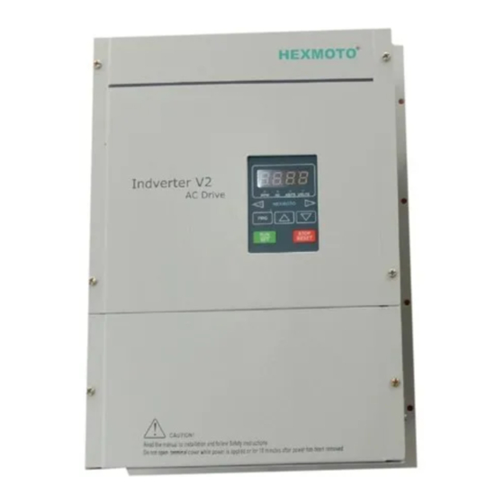
- Page 13 Indverter V2 Manual With Natural Cooling 2.2kW to 7.5kW (3 Hp to 10 Hp) Dimensions: 276 mm x 177 mm x 370 mm ( W x D x H) HEXMOTO Indverter V2 AC Drive AMPS VOLTS HEXMOTO STOP RESET CAUTION ! HEXMOTO Issue 03 Dated 11 November 2009 S/w Ver 12.4...
-
Page 14: Display And Keypad
Indverter V2 Manual 6. DISPLAY AND KEYPAD 7-Segment LED Display window Display LEDs Keypad Keys Description Used as Program Key • Used to enter Programming mode, when the drive is not running. • When the drive is running, this key is used to select RPM, Hz, AMPS,... - Page 15 Indverter V2 Manual Description of Display LEDs Display LED Description LED is ON when display is showing RPM. This selection of display function is based on function code 01 or operation of PRG key while drive is running LED is ON when display is showing Frequency. This selection of display...
-
Page 16: Installation And Commissioning
Indverter V2 Manual 7. INSTALLATION AND COMMISSIONING WARNING • Please follow the instructions in the manual before installation and commissioning • Ensure to disconnect all power lines to the drive before handling or commissioning • Input power cable must be connected tightly and the equipment must be grounded securely using proper grounding techniques •... - Page 17 Indverter V2 Manual Installation of the inverter should be done with following spacing/ clearance from panel doors/walls or other modules. This is required to maintain enough air circulation and ease of identification and wiring. 100 mm 50 mm 50 mm...
- Page 18 Indverter V2 Manual Prepare control and power cables as per the recommendations and ratings mentioned in “ Recommended cable type and terminations”. Grommets are provided to prevent entry of dust into the module inner space. Before connecting input power supply or motor to the drive module, ensure that motor shaft is free to rotate and check for motor winding short circuit or Grounding faults.
- Page 19 Indverter V2 Manual Description of Power Connection INPUT OUTPUT - VE INPUT AC REACTOR FUSE AND MCCB OUTPUT INPUT 3-PHASE 50Hz/60Hz 3-PHASE MOTOR 415V +10% -15% NEG, -VE : DC Reactor Terminals R, Y, B : Input Power Terminals U, V, W...
- Page 20 Indverter V2 Manual Control Circuit Interface NPN CONNECTION PNP CONNECTION USING EXTERNAL SUPPLY (12 TO 24DC) HEXMOTO Issue 03 Dated 11 November 2009 S/w Ver 12.4 Controls Pvt.Ltd...
- Page 21 Indverter V2 Manual Analog input connections 10VA VOUT Differential Input from PLC Potentiometer interface Analog Meter Relay Outputs Sl.No Name Description Fault Relay Normally Closed contact (230VAC / 24 VDC, 2A) Fault Relay Common (230VAC / 24 VDC, 2A) Fault Relay Normally Open contact (230VAC / 24 VDC, 2A)
- Page 22 Indverter V2 Manual CAUTION • All digital inputs are sensed as enabled based on the type of connection as shown in Control circuit diagram. • All analog inputs and outputs are with reference to GA terminal. Except in case of AI+/AI- terminal where differential input is provided •...
- Page 23 Indverter V2 Manual Recommended Cable type and termination Control Cable wiring details Tool: Screw driver blade size: 0.6 x 3.5 mm Recommended 0.14 mm to 1.5mm (26 to 16 AWG) Conductor size Conductor strip length 6 mm ( 8 mm for twin wires for looping)
- Page 24 10% usage rate. Wiring length between inverter and braking unit must be less than 5 Meters Braking unit is in-built in all the Indverter V2 Type modules. Only braking resistor of sufficient capacity must be connected to get good braking performance.
-
Page 25: List Of Parameters
Indverter V2 Manual 8. LIST OF PARAMETERS Function Name Data Code Selection Description Range Factory accuracy Setting Parameter 0000 Locked 0000 to 0001 0001 0001 Lock 0001 Un-Locked 0000 RPM Display 0001 Hz Display 0000 to 0003 0001 0001 display... - Page 26 Indverter V2 Manual Function Name Data Code Selection Description Range Factory accuracy Setting 0000 Disable 0001 Display Keypad 0002 Analog VIN TB 0003 Analog AI+ AI- Voltage Aux Enable 0004 Analog AI+ AI- Current 0000 to 0007 0001 0000 0005...
- Page 27 Indverter V2 Manual Function Name Data Code Selection Description Range Factory accuracy Setting 0000 Same as FOR/REV TB St 4 St 3 St 2 St 1 0001 St1, St2, St3 and 0002 St4 represents 0003 Arun Dir Step1, Step2, 0004...
- Page 28 Indverter V2 Manual Function Name Data Code Selection Description Range Factory accuracy Setting Maximum value for VIN_Max Voltage input through 0000 – 0100 0001 0095 VIN TB 0000 No Filter VIN_Filt 0000 – 0006 0001 0002 0001 to 50Hz to 1 Hz Digital...
- Page 29 Indverter V2 Manual Function Name Data Code Selection Description Range Factory accuracy Setting 0000 Motor Running 0001 Drive accelerating ACC 0002 Drive decelerating DEC 0003 Forward Motion 0004 Reverse motion 0005 DC Injection braking Heat sink Over 0006 temperature 0011...
- Page 30 Indverter V2 Manual Function Name Data Code Selection Description Range Factory accuracy Setting Arun Seconds Acceleration time Step2 0001 to 9999 0001 0010 Step-2 Acc Arun Seconds Acceleration time Step3 0001 to 9999 0001 0010 Step-3 Acc Arun Seconds Acceleration time Step4...
-
Page 31: Description Of Parameters And Programming
Indverter V2 Manual 9. DESCRIPTION OF PARAMETERS AND PROGRAMMING Function codes and data for setting up drive functionality are described below in detail. Understanding different modes of operation of drive controller is essential before setting up the drive parameters. Operation of the drive controller is divided into 5 modes... - Page 32 Indverter V2 Manual Step-1 Selecting a Function code Ready To Run Press key Function Code Use Up/Dn key To select function code Display P 01 00.00 P 00 P 00 P 81 Back to Ready To Run Step-2 Modify Function data...
-
Page 33: Serial Communication Interface
Indverter V2 Manual 01 LED Display By default, drive is configured to display Set Frequency when in Ready To Run Mode and Running frequency in Run mode. Setting Para 01 to various other options such as Motor RPM, Motor Current, and DC bus voltage will enable user to view these values in the same LED display. - Page 34 Indverter V2 Manual 03 Main Speed Reference Speed or Frequency reference is given to the drive controller using Setting 0000 Display keypad UP/DOWN keys Use UP/DOWN keys on display unit to increase or decrease speed reference 0001 Analog input from VIN terminal on TB Potentiometer input using 10VA and GA from TB.
- Page 35 Indverter V2 Manual 07 Starting Frequency In some cases the motor may not be able to develop the required Starting Torque. In these cases the Starting Frequency will be increased. If the set frequency is less than Start Freq, drive cannot be started.
- Page 36 Indverter V2 Manual 15 Electronic Thermal Overload 1Hz to 5 Hz By default Thermal overload function is disabled. Time 5 Hz to 10 Hz Selection 0001 Separately Cooled Motor 10 Hz to 15 Hz When the motor is cooled from an external fan at...
- Page 37 Indverter V2 Manual 20 Aux Enable When Para 20 is disabled, by setting as 0000, X3 terminal is used for multispeed functionality. If set to any of the selection from 0001 to 0007 as described in “List of Parameters”, Auxiliary function is enabled.
- Page 38 Indverter V2 Manual 29-30 JOG Acc – JOG Dec Acceleration and deceleration times set here are selected by the drive if JOG terminal on control TB is activated. This selection remains as long as JOG is enabled. 31 JOG Frequency This is the set frequency for JOG Operation.
- Page 39 Indverter V2 Manual 45 PWM Frequency Certain combination of switching frequencies for particular motor load characteristics can create oscillations in the motor performance due to resonance. User can vary the switching frequency to avoid such oscillations. This is also called as “switching frequency” or “Carrier frequency” in Inverter drives terms.
- Page 40 Indverter V2 Manual Voltage Input from VIN terminal on TB Para 03 set to 0001 TB Analog input 10VA Frequency Para 52 Para 53 Para 54 Para 55 Reference VIN_Min VIN_Max VIN_Filt VIN_Neg Voltage Input from AI+ / AI- Para 03 set to 0002...
- Page 41 Indverter V2 Manual 62 OL Warn Para 65 set to 0016 Programmable relay RL2 on Control card can be Current operated for over load warning. OL Warn data set here is the percentage of motor current for which Relay RL2 switches ON.
- Page 42 Indverter V2 Manual 68 JOG TB Select By default the selection 0000 corresponds to JOG input. JOG function works with FOR/REV terminals for direction of rotation. JOG input must be activated along with FOR/REV input for JOG operation. If THR function is chosen, motor thermal NC contact must be connected between JOG and GD inputs.
- Page 43 Indverter V2 Manual SERIAL COMMUNICATION INTERFACE The drive controller can be remotely controlled with RS485 link provided on Connector CN3. The communication is implemented using RS485 Serial communication with MODBUS protocol specification version V1.1a RTU. Usually, the drive controller works as one of the slaves to a Master PC or Host system. When programmed as a slave using Para 66, it should be ensured that the Slave address of the controller is unique among the other slaves.
-
Page 44: Maintenance And Troubleshooting
Indverter V2 Manual 11. MAINTENANCE AND TROUBLESHOOTING Preventive Maintenance Routine maintenance and inspection are essential for reliable operation of the drive module. Routine maintenance must involve the following activities 1. Inspection of cooling fans and its operation 2. Cleaning of dust accumulated near the cooling fans, Heatsink and other terminals by blowing dry air. - Page 45 Indverter V2 Manual related to input power to the drive system, Electro-dynamometer type watt meter in 2- wattmeter configuration is preferred. Important Notes on Measurement of voltages Measurement of DC Voltage can be done between Power terminals POS and NEG. For 415 V 3- Phase AC inputs, the DC voltage expected is around 550V Average Measurement of Input AC voltages can be done at INPUT terminals between R-Y,Y-B and B-R.
- Page 46 Indverter V2 Manual • Over current during acceleration is Acceleration time displayed when the load current increased. crosses more than 200% of the motor current during acceleration. Check whether drive rating is sufficient for motor connected. If the fault persists even when...
- Page 47 Indverter V2 Manual Hexmoto Controls Pvt. Ltd Plot No. 4-A(Part) Belavadi Industrial Area, Mysore – 570 018 INDIA Phone: 91- 821- 4282140 91- 821- 4280040 Email :hexmoto@yahoo.com Website: www.hexmoto.com HEXMOTO Issue 03 Dated 11 November 2009 S/w Ver 12.4 Controls Pvt.Ltd...
Need help?
Do you have a question about the Indverter V2 and is the answer not in the manual?
Questions and answers