Advertisement
Quick Links
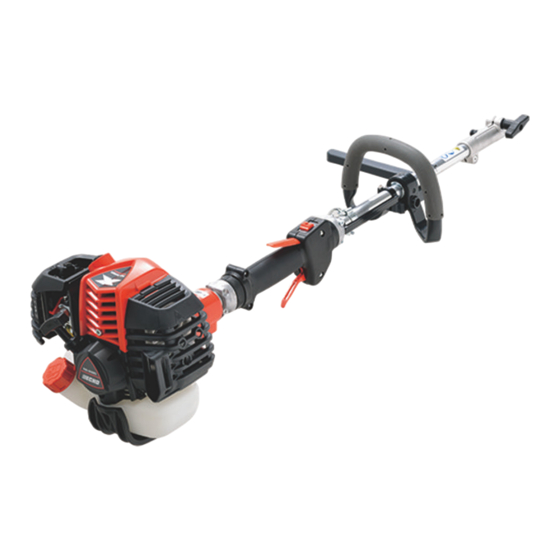
Kit 90206 and 90207includes:
Part Number
Description
A556001760
Clutch Drum
61092255931 Main Pipe Fixture
90070100012 Drum Retaining Ring
C506000470
Flexible Drive Cable
P021051520
Gear Case Assy (90206 1.62 Sq Drive)
P021051360
Gear Case Assy (90207 2.07 Sq Drive)
DISASSEMBLY
1. Remove Spark Plug, and Air Filter Cover. Remove bottom and side
Muffler Cover mount screws using a T27 torx driver. Remove Muffler
Cover by rotating up to disengage from Engine Cover hinge.
2. Remove Clip holding Throttle Cable on carburetor Swivel. Rotate
carburetor rotor to disengage Throttle Cable end from Swivel.
Note: Clip must be reused, do not deform original shape.
Use 10mm open end wrench to loosen Flange Nut holding Throttle
Cable and remove cable from carburetor bracket.
3. Remove (2) Engine Cover T27 screws: rear center, and top left with
torx driver. Remove Engine Cover.
4. Loosen T27 Main Pipe Holder screw and remove Cable Clip.
5. Disconnect two (2) Ignition Leads between the Control Handle and
engine, then slide engine off Main Pipe assembly.
X7672340001
12/16
2620 S
F
erieS
i
nStallation
P/N 90206
P/n 90207
Tools Required:
•
External Snap Ring Pliers w/.053 Tip
Qty
•
Cupped Pliers
1
•
Flat-Blade Screwdriver
1
•
10mm Wrench
1
•
T27 Torx Driver
1
•
Soft Mallet
1
•
W-D 40
1
•
Press
•
Rubbing Alcohol
D
S
lex
rive
haFt
i
nStructionS
SrM-2620
For
SrM-2620t
For
Remove
Flange
Clip
Nut
Nut
Remove
K
it
1
Advertisement

Related Manuals for Echo 2620 Series


Summary of Contents for Echo 2620 Series
- Page 1 2620 S erieS rive haFt nStallation nStructionS P/N 90206 SrM-2620 P/n 90207 SrM-2620t Kit 90206 and 90207includes: Tools Required: • External Snap Ring Pliers w/.053 Tip Part Number Description • Cupped Pliers A556001760 Clutch Drum • Flat-Blade Screwdriver 61092255931 Main Pipe Fixture •...
- Page 2 6. Remove two (2) bottom T27 Fan Cover Protector screws, and one (1) drive housing clamping screw. Remove orange outer Fan Cover Protector. Remove ignition wires from gray Fan Cover. 7. Remove upper right and upper left T27 screws from gray Fan Cover and remove Fan Cover from engine.
- Page 3 13. Press Clutch Drum from Fan Cover. The press tool diameter should be no more than 11mm or (7/16 inch) in order to clear inner bearing ID. Note: The Clutch Drum shaft fits tightly in the Fan Cover bearings requiring a high press load to push the shaft through the bearings. Support the Fan Cover so it does not rest on the cover Locating Pins.
- Page 4 Main Pipe. Install and tighten locat- ing screw. Tighten gear Case clamping screw. 27. Lightly coat the Flexible Driveshaft with ECHO PowerBlendX or lithium grease then install Driveshaft into Main Pipe. Driveshaft end should...
- Page 5 28. Connect the two (2) Ignition Leads between the Control Handle and engine then slide engine onto Main Pipe assembly. 29. Position Cable Clip under Main Pipe then over Throttle Cable and Ignitions Leads. Slide clip tangs under T27 screw head then tighten Main Pipe clamping screw.
- Page 6 REPLACEMENT MANUALS: Operator's, Parts, and Safety Manuals may be obtained from ECHO, or may be down- loaded free from ECHO's website. Make sure you know the model number and serial number of your unit so you can obtain the correct manual.