Table of Contents
Advertisement
Advertisement
Table of Contents

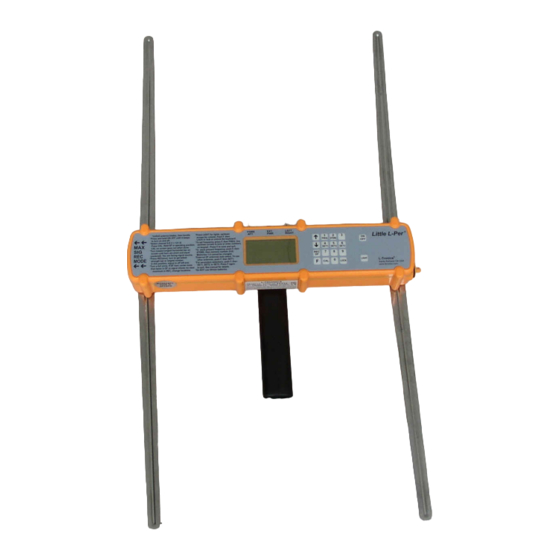
Summary of Contents for L-Tronics Little L-Per LL Series
- Page 1 ® LL Series Little L-Per Portable Direction Finder OPERATING MANUAL...
-
Page 2: Table Of Contents
Typical alkaline battery life 30 hours Audio output 0.3W, 8 ohms. Weight with batteries 29 oz. Indicates areas of latest revisions. ® Copyright 2006 and 2008 by L-Tronics , 5546 Cathedral Oaks Rd., Santa Barbara, CA 93111. www.ltronics.com. All rights reserved. March 2008... -
Page 3: Introduction
With the LL Se- External antenna jacks allow for connection ries: ® of L-Tronics magnetic, flexible, and aircraft antennas, as well as other antennas such 1. It is not necessary to change anten- as beams. A third connector on top of the nas when changing frequencies. -
Page 4: Details On The Operating Screen (Display)
DETAILS ON THE OPERATING SCREEN (DISPLAY) Figure 1. Display Screen Condition Indicators 5. Battery condition bar Figure 1 shows the operating screen in 6. Signal strength bar DF mode illustrating the various condition 7. Attenuation flags indicators. 8. Receiving frequency in MHz 9. -
Page 5: Assembly For Operation
ASSEMBLY FOR OPERATION To turn the receiver on, hold the PWR key down for 2-3 seconds. It will beep and The receiver is shipped with a protective the display will come on. To turn the DF off, film covering the display. Carefully peel this hold the PWR key down for one second. -
Page 6: Details On Operation
Finding Techniques section (page 13). When a vehicle is equipped with two sets ® of L-Tronics DF antennas, one mounted fore-aft and the second left-right, the coax leads are connected to the appropriate BNC jacks on top of the receiver. The display on... -
Page 7: Operation In The Df Mode
These settings are not changeable from operator’s arm, or curious onlookers gather the keyboard. If the DF ever gets into an close by. unknown or unusable state, pressing one of these keys will reset to factory program- Operation in the Receive Mode ming. -
Page 8: Changing Frequency
If the DF is being used with external an- ® memory. Changing frequency in this way tennas, such as the L-Tronics LVA series does NOT require a new calibration. For magnetic antennas, only the receiver will be example, 121.5000 MHz loaded from mem-... -
Page 9: Storing A Frequency
It does not affect DF operation. tennas will all be detected. Adding a 470 The default is AM below 137 MHz and ® ohm resistor to the L-Tronics LHBM-1 above 235 MHz and FM elsewhere. beam and LVA-1 monitor antennas will al- 2. -
Page 10: External Power And Audio
SET2 (F, SET2, 1, connector with a 4 wire, 6 foot cable is F.) This upgrade can be added at the fac- ® available from L-Tronics as part number tory to earlier units. 120014. The mating... -
Page 11: More About Batteries
distorted. This is not a receiver fault. It also The screws holding the built-in antennas ® means that reception of older ELTs, which are sealed with Locktite . Should one ever ®7 have wider frequency tolerances, may be work loose, a drop of Locktite , preferably improved by tuning the DF receiver fre- 290 grade (green) should be applied to hold... - Page 12 cost, and resistance to corrosion. New alka- discharge rate than alkaline. These should line batteries will run the DF for about 30 be considered only if alkaline batteries are hours. When the bar on the battery indicator not available. ® symbol on the front panel display disap- Oxyride batteries from Panasonic pears, about one hour of operating time re-...
-
Page 13: Direction Finding Techniques
DIRECTION FINDING TECHNIQUES Following is a summary of Direction Finding tion and watching the display. The bar should Techniques. More information can be obtained darken to the left, center at approximately oppo- from our publications LHTM-1, “Air and Ground site the ELT, darken on the right side, then cen- Direction Finding,”... -
Page 14: Reflectors
REFLECTORS Blocked Signal, Multiple Reflectors Reflections cause almost off of the problems in transmitter (ELT and EPIRB) location. Multiple reflections coming from the same Solid conductive objects, like metal buildings general direction when the direct signal is and mountains, both reflect and block the signal. blocked will cause much the same results as a ®... -
Page 15: Direction Finding Inside A Building
Direction indications is often not useful inside a building because of so many reflections near the receiver. If there are a number of aircraft inside, it is often faster to rely only on strength readings. Strength response is not directional in DF mode.
Need help?
Do you have a question about the Little L-Per LL Series and is the answer not in the manual?
Questions and answers