
Summary of Contents for Redline Communications AN-50
- Page 1 AN-50 System User Manual AN-50 System User Manual [PTP/PMP] Manual 70-00001-01R00 Release 2.01...
- Page 2 AN-50 System User Manual Page 2 of 76 Redline Communications …..solving the first mile challenge.
- Page 3 Disclaimer This manual was designed to help you install, use and troubleshoot the Redline AN-50 Broadband Fixed Wireless (BFW) system. Every effort has been made to ensure the accuracy of the material provided herein; however, Redline assumes no responsibility regarding the use of the material.
- Page 4 AN-50 System User Manual FCC & IC Information 1 - This equipment has been tested and found to comply with the limits for a Class A digital device, pursuant to Part 15 of the FCC Rules. These limits are designed to provide reasonable protection against harmful interference when the equipment is operated in a commercial environment.
-
Page 5: Table Of Contents
Unpacking the AN-50 System ................. 13 AN-50 System Mode of Operation ................14 The AN-50 Terminal at a Glance................15 6.1. The AN-50 System’s T-58 Transceiver / Antenna at a Glance ....... 17 AN-50 System Installation ..................19 7.1. General Site Survey ..................20 7.2. - Page 6 AN-50 System User Manual LIST OF TABLES Table 1: Max. Operational Power Per Antenna (in dBm) ..........31 Table 2: Max. Operational Power Per Channel (in dBm) vs. Modulation......31 Table 3: System Power Diagnostics ................47 Table 4: Wireless Link Diagnostics ................. 48 Table 5: Wireless Signal Diagnostics................
- Page 7 Figure 8: Radio Deployment Options ................21 Figure 9: IF Cable ......................22 Figure 10: AN-50 Terminal Connected To Switch / Router / Hub ........23 Figure 11: AN-50 Terminal Connected To Host Computer ..........24 Figure 12: AN-50 Terminal LAN Ethernet Port Pinout ............ 24 Figure 13: Aligning The Antenna - Vertical Mount ............
-
Page 8: Getting Started
4. Install the indoor terminal (Section 7) 5. Configure the system via a host computer and web browser interface (Section 8) 6. Ensure the Mac address of the remote AN-50 has been properly configured (see Section 8.2.1) on the local unit 7. - Page 9 PMP mode of operation can operate at over 15 miles ( 24 km) , depending on power limits mandated by regional regulation. The AN-50 system is a Class A digital device for use in a commercial, industrial or business environment.
-
Page 10: Important Safety Information
Disconnect the power before cleaning. Protect the unit by disconnecting the power if it is not used for long periods of time. Locate the AN-50 terminal on a stable horizontal surface or mount it securely in a 19” Telco rack. - Page 11 AN-50 System User Manual The following symbols may be encountered during installation or troubleshooting. These warning symbols mean danger. Bodily injury may result if you are not aware of the safety hazards involved in working with electrical equipment and radio transmitters. Familiarize yourself with standard safety practices before continuing.
-
Page 12: Important Service Information
The unit does not function after following the operating instructions outlined in this manual. b) Liquid has been spilled, a foreign object is inside or the AN-50 terminal has been exposed to rain. c) The product has been dropped or the housing is damaged. -
Page 13: Unpacking The An-50 System
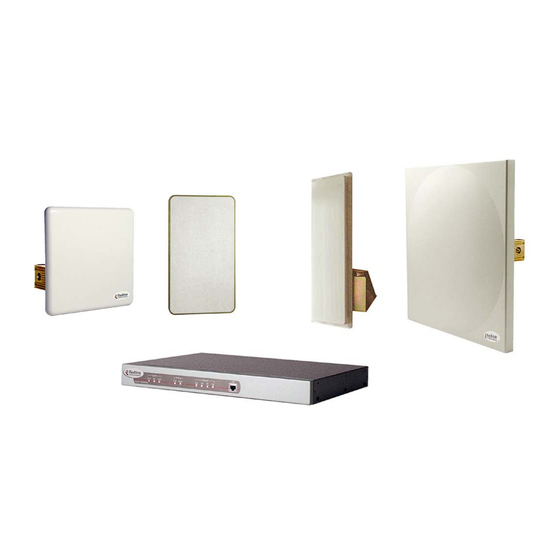
AN-50 System User Manual The AN-50 system comes packaged with the following major items (refer to Figure 1 for a pictorial view): • AN-50 Terminal (indoor unit) • AN-50 Radio (outdoor unit): T-58 Transceiver Antenna • Antenna Mounting Bracket: • Power Cord and outdoor IF Cable (100 ft. / 30.5 m) •... -
Page 14: System Mode Of Operation
A single sector AN-50 PMP implements a distributed wireless L2 switch, with one uplink port located on the sector controller (master) distributing bandwidth to a variable number of subscriber stations (slaves). -
Page 15: The An-50 Terminal At A Glance
AN-50 System User Manual The front panel of the AN-50 terminal includes a LAN interface and three main status indicators; System, Wireless, and Ethernet. The rear of the terminal includes the power cord connector and an F-Type female connector for the IF cable. -
Page 16: Figure 3: Front Panel - Wireless
AN-50 System User Manual B) Wireless Status Indicators The Wireless portion of the front panel features two LEDs; Link and Signal, as shown below. Figure 3: Front Panel - Wireless Link – For a slave terminal, the “Link” LED lights solid green when the radio link to the master terminal is established and the LED will turn off if the link is lost. -
Page 17: The An-50 System's T-58 Transceiver / Antenna At A Glance
Col – The “Col” LED flashes in amber when collisions are detected on the Ethernet port. D) The LAN Interface The LAN interface is a 10/100 BaseT Ethernet port, which is used to connect the AN-50 terminal to either the core network or to a host computer. A router or switch is often used to complete the connection to the core network, as shown in the figure below. -
Page 18: Figure 6: An-50 Radio With Vertical Mount
The Redline vertical mount bracket can accommodate 1 ¾” to 4 ½” (4.45 cm – 11.45 cm) OD masts found on many commercial tower installations. Before connecting the AN-50 system, it is important to review the safety tips provided at the beginning of this manual. -
Page 19: System Installation
T-58 Transceiver (located outdoors), and carries the transmitted and received signal, DC power for the AN-50 radio, as well as control and reference signals. Note that the provided IF cable is meant for exterior use, and should be used for only minimal interior runs to connect to the terminal. -
Page 20: General Site Survey
7.1. General Site Survey The first step in installing the AN-50 system is to conduct a general site survey. Although the installation steps are relatively straightforward, they do involve some construction and electrical work, which is best performed by a professional installer. -
Page 21: Installing The Antenna
Identify potential sources of RF interference. Test for possible RF interference on the roof-top or tower by utilizing appropriate test equipment. RF interference arises from any other wireless system operating within the same frequency band as the AN-50. Note that the AN-50 system supports nine different overlapping channels within the 5.8 GHz band and has the ability to use up to five of these channels at any one cell site;... -
Page 22: Running The If Cable
1mm (.042 inches) or longer than 1cm (0.38 inches) to avoid damage to the T-58 and AN-50 connectors. If the core diameter exceeds 1mm, use solder type ‘F’ connectors that do not exceed these dimensions. -
Page 23: Installing The Terminal
1/8 of a turn. 7.4. Installing The Terminal Once the AN-50 terminal and the radio are connected, the terminal is ready to be installed and configured. The Ethernet data rate is determined automatically, depending on the type of device connected to the system. -
Page 24: Figure 11: An-50 Terminal Connected To Host Computer
AN-50 System User Manual The AN-50 terminal may also be connected directly to the host computer, as shown in Figure 11. In this configuration, a straight-through CAT 5/UTP cable is required to complete the connection. Figure 11: AN-50 Terminal Connected To Host Computer To help you establish other implementations that are not addressed in this manual, Figure 12 provides an illustration of the pinout for the AN-50 terminal LAN interface. -
Page 25: Aligning The Antenna
AN-50 System User Manual indicate power to the unit. The system is now ready to be configured. If the Pwr LED is not on and/or the “Fault” LED illuminates red, there is a problem with the terminal. Refer to the diagnostics section, Section 9 on page 46, for further details on how to address system faults. - Page 26 (9.3 feet) from all persons and must not be co-located or operating in conjunction with any other antenna or transmitter. 3 - The AN-50 System is certified by the FCC and Industry Canada with 5.8 GHz Directional and Parabolic Antennas, listed bellow:...
-
Page 27: System Configuration And Operation Via The Web Interface
Internet. This section describes the procedures for configuring and operating the AN-50 terminal via the web interface. All screens and explanations refer to both PTP / PMP modes of operation unless otherwise specified. -
Page 28: Figure 14: User Name And Password Dialog
AN-50 System User Manual • System Config • System Password • ID Config / Status • Upload Software • Reset button on System Status An example of the user name and password screen is shown in Figure 14. There are 2 users –... -
Page 29: System Configuration
Ethernet and Wireless components of the AN-50 terminal. Note all parameters under System Configuration are global and apply to every subscriber station. To store the parameters into memory, click the Save Configuration button at the bottom of this page. - Page 30 See section 8.6 for additional details. Mode: Sets the AN-50 to serve as the PMP master, PTP master or PMP / PTP slave. One and only one unit must be set as the master. A slave will not communicate with another slave.
-
Page 31: Table 1: Max. Operational Power Per Antenna (In Dbm)
AN-50 System User Manual Table 1: Max. Operational Power Per Antenna (in dBm) Redline’s Minimum Max Conducted Antenna Max EIRP Part Number Antenna Type Application Conducted Power Ratings Gain (dBi) (dBm) Power (dBm) (dBm) 48-00017 Directional, 36 dBm Sector 48-00025... -
Page 32: Id Configuration And Status
AN-50 System User Manual Channel Frequency: specifies the operating channel of the system, within the 100 MHz available in the 5.8 GHz band. The table below specifies the center frequencies of each permitted channel. Channel Frequency 5735 MHz 5745 MHz... -
Page 33: Link Configuration
This screen is displayed through the ID Config / Status screen by clicking the Config button. Please note that this screen will be active only on the AN-50 operating in PMP / PTP master mode. The fields in the Link Configuration screen need to be filled out for each individual subscriber station. -
Page 34: Figure 17: Link Configuration
ID is always zero. After saving the parameter on the Link Configuration screen, the AN-50 system will automatically choose a link ID other than zero. Using the ID Browser, one can search for the specific Link ID associated with the link name. -
Page 35: Wireless Link Statistics
Link Name: Displays the link name from the system memory. The name remains with the system even during power off states, until the operator re-types a new name using this menu field. Link ID: Displays the link ID automatically defined by the AN-50 System for the link name. Page 35 of 76 Redline Communications …..solving the first mile challenge. - Page 36 AN-50 terminal and T-58 Transceiver. Configured Connections: Shows the total number of connections configured for this link. For the current AN-50 revision the system will always display one (1) connection. Link Status Downlink / Uplink: Burst Rate [Mb/s]: Indicates for this wireless link the current Tx burst rate used by the master (downlink) and by the slave (uplink) ..
-
Page 37: Id Browser
AN-50 System User Manual 8.3. ID Browser Figure 19: ID Browser ID Properties: Name: Name of remote unit being searched. Note partial string pattern or entire link name can be input. Type: Defines search criteria based on entity type: Link, Connection or All... -
Page 38: System Information
Located at the top of this page is a graphic interface providing a real-time synoptic view of the AN-50 terminal front panel (refreshed every 30 sec.), plus a summary of general information related to the configuration and status of the local unit. -
Page 39: System Statistics
General: Status Code: An global error code indicating the condition of different components within the AN-50 terminal and T-58 Transceiver as well as the status of all links and connections involving the terminal. See error list below for details: AN-50 PLL Error: The PLL (Phase Locked Loop) section within the AN-50 terminal experienced an error. - Page 40 AN-50 System User Manual Ethernet Status: Rx Packets: Indicates the total number of received packets. RX Packets – Errors: Indicates the total number of packets received with errors Rx Packets - Discarded: Indicates the total number of packets discarded due to full buffer .
-
Page 41: Upload Software
A status screen (see Figure 24) will appear, displaying the number of bytes being transferred from the host computer/server to the AN-50 terminal in real time. The upgrade file size is approximately 1.8 MB, and will take approximately two to four minutes to download from the server to the AN-50 terminal memory. -
Page 42: Figure 24: File Transfer Progress
If errors were introduced during the transfer process as a result of (for example) link degradation, the AN-50 terminal will reject the new software load and provide a warning that the upgrade was unsuccessful. In this case, the operator will need to repeat the upload process. -
Page 43: System Password
AN-50 System User Manual 8.7. System Password The factory default password for the system is "admin" for the administrator’s ID, and “user” for the user’s ID. To change the password, click on System Password from the main menu and apply a new value in the New Password field (see Figure 25) using any alphanumeric combination. -
Page 44: System Logs
8.8. System Logs The System Logs page, shown in Figure 26 below, provides a list of the last forty messages recorded by the AN-50 terminal, describing either system activity or errors that have occurred. Figure 26: System Logs Screen The logs will also indicate if the following transactions were successfully completed: •... - Page 45 A mis- configured TPTP server will also cause this error 209-TFTP error received! The Trivial File Transfer Protocol (TFTP) routine used to download the software to the AN-50 terminal during the Upgrade process failed. Likely cause is disconnected or faulty cable.
-
Page 46: Diagnostics And Troubleshooting
Section 7. This section provides basic diagnostic and troubleshooting procedures to help solve problems that may occur with the AN-50 system. If, after reading this section, you are unable to get the system operating properly, please contact your local Redline representative. -
Page 47: System Power
AN-50 System User Manual All four Ethernet LEDs light for one second, then individual Ethernet LEDs blink twice in the following order: 100, FD, Col, Link. The Fault LED lights for approximately four seconds, then turns off. The two Wireless LEDs remain off for approximately five seconds, then blink once and resume their normal state. -
Page 48: System Fault
AN-50 System User Manual 9.1.2. System Fault If the Fault LED illuminates solid red, it is an indication that there is a serious problem with the system software or hardware. Check the IF cable. A short or long reset may fix the problem. If not, contact your local Redline representative. -
Page 49: Wireless Signal
AN-50 System User Manual 9.1.4. Wireless Signal Signal – The “Signal” LED lights solid green if the system, the link (the (links for a master) and the provisioned connections all operate within configured parameters. Wireless Signal LED will light solid green if the system is operating at an error rate of less than one out of one million packets. -
Page 50: Ethernet Collision
AN-50 System User Manual Table 6: Ethernet Link Diagnostics Symptom Possible Problem Solution No Ethernet Link Poor cable connection between Carefully check all cable (Link LED off) terminal and computer/server connections. or between terminal and switch/router. Wrong type of Ethernet cable... -
Page 51: Troubleshooting The Web Interface
AN-50 System User Manual 9.2. Troubleshooting The Web Interface The section assumes that the status LEDs on the front panel of the AN-50 terminal indicate normal functionality. If, after using HTTP commands to try to log onto the AN-50 terminal the General Information page does not appear on-screen, several possibilities exist. -
Page 52: Broadband Fixed Wireless Primer
• Quicker time to market • Greater portability The AN-50 system functions logically as a transparent bridge, providing all the benefits of a converged IP network, i.e., "IP everywhere". A converged network allows operators to reduce network build out costs significantly by employing standard IP appliances everywhere, from backbone to end-user. -
Page 53: Deployment Scenarios
Deployment Scenarios This section provides a general overview of typical AN-50 Point to Multi-Point (PMP) deployment scenarios. The AN-50 base station PMP system supports both 60 and 90 degree cell sectorization, as illustrated below. Figure 28: Cell Sectorization The advantage of the narrower 60 degree beam antenna is that it achieves higher... -
Page 54: Figure 29: Growing A Network
Note that in some deployment situations involving high tower installations, it may be prudent to install all six antennas and radios initially, and begin with only a single AN-50 system operating out of one of the sectors. Later, as the customer base grows, the other sectors can be easily put online by the addition of only the indoor terminals. -
Page 55: Who Can Benefit From The An-50 System
• Educational Institutions and Campuses A) Carriers The AN-50 system will provide benefits to both Incumbent and Competitive Local Exchange Carriers (ILECs and CLECs, respectively). Although ILECs own and provide services over wireline infrastructures within a specific geographical area, they are faced with the challenges of reaching outlying regions suffering from poor to no service. -
Page 56: Figure 32: Wireless Extension For Carriers
Small Office Home Office (SOHO) and Small to Medium sized Enterprises (SME) located just outside of the downtown core, where there is a lack of infrastructure. As well, the AN-50 is well suited for MTU/MBUs and backhaul for Hotspots/Internet Cafés. High-speed leased lines are expensive and hard to obtain, especially from local telephone companies. -
Page 57: Figure 34: Wireless Solution For Enterprise
Internet content to the student body. Fixed wireless systems such as the AN-50 provide a cost effective means of creating a backbone for connecting existing and new campus buildings to the educational infrastructure to support distance learning and two-way interactive training. -
Page 58: The An-50 Advantage
The AN-50 system has been designed to operate in the 5.8 GHz band, which occupies the license exempt portion of the spectrum. This allows an operator to set up a wireless network without requiring formal consent from the regulatory agent. -
Page 59: The Link Budget Tool
Redline has developed a Link Budget Tool to help characterize the range performance of the AN-50 system for LOS, OLOS (optical line of sight) and NLOS conditions and various system parameters. The Link Budget Tool can be obtained by contacting your Redline certified partner or system integrator. -
Page 60: Table 9: Modulation Scheme Vs. Data Rate
AN-50 System User Manual Table 9: Modulation Scheme vs. Data Rate Modulation Coding Over The Air Coded Burst Average Ethernet Rate Rate (Mbps) Rate (Mbps) Rate (Mbps) BPSK ½ BPSK ¾ QPSK ½ 11.2 QPSK ¾ 16.5 16 QAM ½... -
Page 61: Figure 37: Fresnel Zone Radius Calculation
It defines the power level at which the receiver is sensitive enough to properly detect the signal. For the AN-50 operating in a channel spacing of 20 MHz, the Smin is approximately –96 dBm. -
Page 62: Table 10: Availability Versus Outage Time
(e.g., BPSK) are implemented at long distances. A sample link budget is shown in Figure 38 for the AN-50 system operating in 64 QAM, 3/4 code rating, providing a net burst throughput of 54 Megabits per second (Mbps). This provides an average throughput of 43 Mbps to the Ethernet port. -
Page 63: Figure 38: Link Budget For 64 Qam ¾ Code Rate
AN-50 System User Manual Figure 38: Link Budget For 64 QAM ¾ Code Rate Page 63 of 76 Redline Communications …..solving the first mile challenge . -
Page 64: Figure 39: Fade Margin Graphs For Los, Olos And Nlos
AN-50 System User Manual A fade margin graph for this link budget is given in Figure 39 below for four conditions: LOS (a - blue line), OLOS with the first Fresnel zone obstructed (b - red line), NLOS scattered trees and buildings (c - green line) and heavily treed residential NLOS (d - magenta line). -
Page 65: Table 11: Radar Horizon Ranges For Different Terminal Heights (H And H )
AN-50 System User Manual Table 11: Radar Horizon Ranges For Different Terminal Heights (H and H 25.9 31.3 35.4 38.9 42.0 44.7 47.3 31.3 36.7 40.8 44.3 47.3 50.1 52.6 35.4 40.8 44.9 48.4 51.4 54.2 56.8 38.9 44.3 48.4 51.9... -
Page 66: Appendix
Subscriber Station, based on 18 programmable QoS levels. By configuring AN-50 PMP Configuration tool with the sector parameters (numbers in black) the CIR of each Subscriber Station can be adjusted as desired. Then the AN-50 needs to be configured using the green values that were calculated based on the input provided. - Page 67 AN-50 System User Manual number between 10 and 100 and check to see if the calculated Registration Cycle is below 1000 usec. Lower the entered number to bring the Cycle below 1000 usec. Higher numbers give better efficiency. A good starting number is approximately double the number of subscribers.
- Page 68 AN-50 System User Manual subscribers before looking for new ones. This cycle is a result of the Registration Period set above. Bandwidth Used (%) – Must be less than 100%. 70% is more conservative. If values are too high or above 100%, the user entered a desired CIP higher than the total possible Obtained CIR.
-
Page 69: 10.2. Appendix 1 - Glossary Of Terms
AN-50 System User Manual 10.2. Appendix 1 - Glossary Of Terms AN-50 Redline Communications’ Access Node-50 Broadband Fixed Wireless (BFW) system. Antenna A device for transmitting and/or receiving a radio frequency (RF). Antennas vary in design and frequencies supported. Antenna Gain The measure of antenna performance relative to a theoretical antenna called an isotropic antenna. - Page 70 AN-50 System User Manual Line Of Sight. A clear direct path between two antennas, with no obstructions within the first Fresnel zone. MAC (Media Access Control) A unique number assigned to a network device. It corresponds to the ISO Network Model Layer 2 data link layer.
-
Page 71: 10.3. Appendix 2 - An-50 System Specifications
AN-50 System User Manual 10.3. Appendix 2 - AN-50 System Specifications AN-50 System Specifications System Capability Non-line-of-sight operations, PTP / PMP mode RF Band 5.725 - 5.825 GHz Band Channel Center Channel Freq. 5.735 5.745 5.755 5.765 5.775 5.785 5.795 5.805... - Page 72 Single or dual 110/220/240 VAC (auto-sensing) 50/60 Hz 39W maximum Operating Temperature AN-50 Terminal Operating Conditions: 41F to 104F / 5C to 40C AN-50 Terminal Short-Term Conditions: 23F to 41F and 104F to Range 131F / -5C to 5C and 40C to 55C for up to 16 hours...
- Page 73 AN-50 System User Manual...
- Page 76 302 Town Centre Blvd. • Markham, Ontario • Canada • L3R 08E www.redlinecommunications.com...
Need help?
Do you have a question about the AN-50 and is the answer not in the manual?
Questions and answers