
Subscribe to Our Youtube Channel
Summary of Contents for Smithy MIDAS MI-1220 LTD
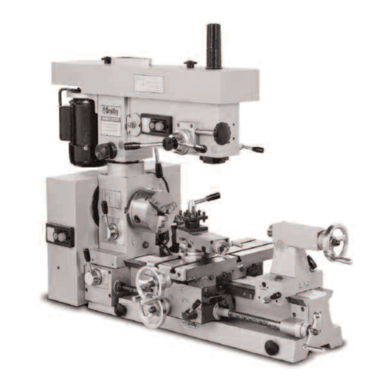
- Page 1 MIDAS 1220 & 1230 LTD Combination Lathe - Mill - Drill OPERATOR’S MANUAL Updated Feb. 2019 170 Aprill Dr., Ann Arbor, MI, USA 48103 1-800-476-4849 www.smithy.com...
- Page 2 While every precaution has been taken in the preparation of this manual, Smithy Co. shall not have any liability to any person or entity with respect to any loss or damage caused or alleged to be caused directly or indirectly by the instructions contained in this manual.
-
Page 3: Table Of Contents
Table of Contents Chapter 1: Introduction Introduction ..........1-1 Chapter 2: Safety Safety . - Page 4 Lathe ...........5-7 Adjusting Gibs .
- Page 5 Setting Up Work in a Chuck ....... .10-7 Mounting Work in a Four-Jaw Independent Lathe Chuck .
- Page 6 Chapter 17: Milling Milling ..........17-1 Holding Milling Cutters .
- Page 7 Chapter 21: Ml-1220 LTD Full Specifications M l-1220 LTD Full Specifications ......21-1 Chapter 22: Parts Diagram and Parts List Tensioner Assembly Diagram ......22-1 Millhead Assembly ........, ..22-3 Tailstock Assembly ........22-8 Bed and Table Assembly ......... 22-11 Powerfeed Engagement .......
-
Page 8: Introduction
If you have comments about this operator’s manual, or if you have a project you’d like to share with other Smithy owners, contact Smithy Co., PO Box 1517, Ann Arbor, Michigan 48106-1517. -
Page 9: Safety
Chapter 2 Safety Your workshop is only as safe as you make it. Take responsibility for the safety of all who use or visit it. This list of rules is by no means complete, and remember that common sense is a must. 1. - Page 10 13. Use the correct tool for the job. Don’t try to make a tool into something it isn’t. 14. Keep your mind on your work. Pay attention to these simple rules and you will spend many safe, enjoyable houses in your workshop. Note: Your safety depends largely on your practices. Or Visit www.smithy.com...
-
Page 11: Chapter 3: Caring For Your Machine
Any rust spot or battering of the ways, any chips or grit between close-fitting parts, will affect the accuracy of this fine tool. Follow these guidelines whenever you use your Smithy machine: 1. When you finish working, wipe machined surfaces with a clean, oily rag. Never leave the machine without this thin film of protective oil all over parts that might rust, especially ground finished parts. -
Page 12: Chapter 4: Basic Parts Of The Mi-1220 Ltd
Its function is to support the cutting tool rigidity and move it along the bed for different operations. It locks into place by tightening the carriage lock with the setscrew on the backside of the carriage. Or Visit www.smithy.com... - Page 13 Midas 1220 LTD Operator’s Manual 3. Compound Rest. Mounted on the cross slide, the compound rest swivels to any angle horizontal to the lathe axis to produce bevels and tapers. Cutting tools fasten to a toolpost on the compound rest. The calibration on the front of the base are numbered in degrees from 60 right to 60 left.
- Page 14 See figure. 4.2. Setover Screw Rgiht Treslte Setscrew Figure 4.2 Tailstock base locking bolts. Or Visit www.smithy.com...
-
Page 15: Chapter 5: Uncrating And Setting Up The Mi-1220 Ltd
Moving a machine tool can be dangerous. Improper techniques and methods may injure you and/or damage the machine. To find a professional to move and site your Smithy machine, look in your local Yellow Pages under “Machine Tools, Moving and/or Rigging”. -
Page 16: Millhead
Be careful no to lose them. Bolts Figure 5.2 The chuck attaches to the spindle flange with three bolts. The one bolt located on the other side of the spindle does not show. Or Visit www.smithy.com... -
Page 17: Three Jaw Chuck
Selecting a Location There are several major considerations for selecting a location for your Smithy. Operation is from the apron side, so allow at least 40” to 48” clearance in front of the machine. -
Page 18: Cleaning And Lubricating The Mi-1220 Ltd
5: Uncrating and Setting Up the MI-1220 LTD Cleaning and Lubricating the MI-1220 LTD Smithy machines are shipped with protective grease coating called cosmoline. Use WD-40 or non-corrosive kerosene to remove the cosmoline. Once you have your MI-1220 LTD set up and positioned correctly, you are ready for lubricating. -
Page 19: Oiling The Carriage
Midas 1220 LTD Operator’s Manual Open the gearbox door to expose the pick-off gears. Oil the button in the casting behind the D gear. Then put a few drops of oil on the teeth of all the gears. Grease the zerk on the A gear shaft. -
Page 20: Oiling The Leadscrew
To keep your machine in peak condition, lubricate it daily after removing any debris. Do not fill the gearbox sight glass more than half way. Too much oil will make the motor lug and sling oil out form behind the chuck and inside the belt box. Or Visit www.smithy.com... -
Page 21: Adjusting Belt Tension
Midas 1220 LTD Operator’s Manual Adjusting Belt Tension The MI-1220 LTD has two belt tensioners installed by the factory. One for the millhead and the other one for the pulley box. Figure 5.11 Mill belt Mill Locate the “L shaped” lever and a thumbscrew at the top of the mill motor. Loosen the thumbscrew and then rotate the lever to increase or decrease the belt tension. -
Page 22: Reducing Backlash
If there is still excess backlash, place one or more shim washers between the large shoulder of the cross feed screw and the bush bearing. Ask a Smithy technician about our antibacklash shim washer kit, Item number K99-190. -
Page 23: Lathe Run In
Midas 1220 LTD Operator’s Manual 4. Start the mill motor by pushing in the green start button. After a few minutes, push in the red stop button and allow the motor to stop. Flip the yellow switch cover and switch it to the opposite position and repeat the above procedure. -
Page 24: Setting Lathe And Mill Speeds For The Mi-1220 Ltd
Set mill speeds using various combinations of the mill belts. For 315 RPM, place belt A/B in position 4 and belt B/C in position 1. For 500 RPM, leave belt A/B belt in position 4 and move the B/C belt to position 3. 5-10 Or Visit www.smithy.com... -
Page 25: Chapter 6: Turning
Chapter 6 Turning The lathe rotates a workpiece against a cutting edge. With its versatility and numerous attachments, accessories, and cutting tools, it can do almost any machining operation. The modern lathe offers the following: • The strength to cut hard, tough materials •... - Page 26 3” Table 6.1 Cutting Speeds for Various Diameters Table provides exact speeds (rpm). It does not take machine speed limitations into account. Determine the desired rate of speed and find the closest speed available on your machine. Or Visit www.smithy.com...
-
Page 27: Gear Ratios
Midas 1220 LTD Operator’s Manual • The means to hold the cutting point tight • The means to regulate operating speed • The means to feed the tool into or across, or into and across, the work, either manually or by engine power, under precise control •... -
Page 28: Chapter 7: Metal Theory
Because steel expands when heated, it is a good idea, especially when working on long shafts, to check the tightness of the lathe centers frequently and make sure workpiece expansion does not cause centers to bind. Or Visit www.smithy.com... - Page 29 Midas 1220 LTD Operator’s Manual High- Low-Carbon Carbon Alloy Steel Aluminum Cast Iron Bronze Steel Steel Normalized Alloys Annealead Speed (sfm) Roughing Finishing Feed (ipr) Roughing 0.010-0.202 0.101-0.020 0.010-0.020 0.015-0.030 0.010-0.020 0.010-0.020 Finishing 0.003-0.005 0.003-0.005 0.003-0.005 0.005-0.010 0.003-0.010 0.003-0.010 Table 7.1 Cutting Speeds and Feeds for High-Speed-Steel Tools In everyday lathe operations like thread cutting and knurling, always use cutting oil or other lubricant.
- Page 30 The four-turret toolpost lets you mount up to four different tools at the same time. You can install all standard-shaped turning and facing tools with 1" or smaller shanks. The centerline is approximately 5/8" above the bottom of the turret. Smithy also offers quick-change tool sets that greatly speed up lathe operations. Contact a Smithy technician for details.
-
Page 31: Chapter 8: Grinding Cutter Bits For Lathe Tools
Chapter 8 Grinding Cutter Bits for Lathe Tools High Speed Steel Cutters The advantage of HSS cutter bits is you can shape them to exact specifications through grinding. This lets you grind a stock shape into any form. Stock shapes come in an assortment of types, including squares, flats, and bevels. - Page 32 Figure 8.4. Cutter Bit Grinding Wheel 1. Left Side 2. Rigt Side 3. End 4. Radius 5. Top Rake Clearance Clearance Clearance Figure 8.3 Grinding sequence for an unground cutter bit. Or Visit www.smithy.com...
-
Page 33: Materials Other Than Steel
Midas 1220 LTD Operator’s Manual Oilstone Figure 8.4 When honing, draw the cutter away from the cutting edge across the oilstone. Materials Other Than Steel As pointed out earlier, when grinding HSS cutters, we determine cutting angles primarily by strength requirements, not keenness requirements. Angles and rakes for general industrial shop use are established. -
Page 34: Special Chip Craters And Chipbreakers
(Figure 8.8). Examine the gauge and cutter before a light. When the cutter is ground perfectly, no light streak shows between tool and gauge. Use a grinding chart for other rakes. Figure 8.8 Insert the point into the nearest seized V in the center gauge. Or Visit www.smithy.com... -
Page 35: Acme Or Other Special Threads
Midas 1220 LTD Operator’s Manual Acme or Other Special Threads Thread gauges are available for all standard threads. Before grinding such cutters, ascertain the correct pitch angle of the particular thread profile. For example, the pitch of an acme thread is 29° to a side, and the toolpoint is ground back square to an exact thread profile that requires a different end width for each thread size. -
Page 36: Chapter 9: Setting Up Lathe Tools
In steel, the harder the material, the less above center (Figure 9.2, left). Exceptions are soft brass, aluminum, and materials that tend to pull or tear. When machining these materials, set the cutter on dead center (Figure 9.2, right). Or Visit www.smithy.com... -
Page 37: Threading Tools
Midas 1220 LTD Operator’s Manual Figure 9.2 The harder the steel (left),the less above center you set the cutter point. For soft brass and aluminum (right), set the cutter on dead center. When cutting toward the headstock on most turning and threading operations, swing the compound rest to hold the shank of the toolholder at an angle. -
Page 38: Cutoff, Thread Cutting And Facing Tools
Some machinists prefer to position the tool slightly above center when boring. With the bit above center, if a tool chatters it deflects down into empty space instead of into the workpiece. Figure 9.6 For boring and inside threading, the cutter point is at dead center. Or Visit www.smithy.com... -
Page 39: Chapter 10: Setting Up With Centers, Collets And Chucks
Chapter 10 Setting Up with Centers, Collets, and Chucks Before setting work up on centers, make sure the spindle and tailstock centers align accurately. Do this by inserting a center into the nose spindle and inserting the tailstock center into the tailstock ram. Then move the tailstock toward the headstock until the centers touch (Figure 10.1). - Page 40 Next, drill and countersink the centers to conform to the profile of the lathe centers. This is best done with a combination center drill/countersink held in the tailstock arbor chuck. The centers now will take the lathe centers without play or chatter. 10-2 Or Visit www.smithy.com...
-
Page 41: Mounting Work Between Centers
Midas 1220 LTD Operator’s Manual If a combination drill is not available, you can drill centers with a small drill and countersink them with a drill of sufficient diameter ground to a 60° point. A 60° taper is standard for lathe center points. Correct center depth is given in Figure 10.6. Take care to get an accurate 60°... -
Page 42: Using A Clamp Dog
T-slotted, drilled all over, or slotted and drilled. Workpieces mount on such faceplates with T-slot or standard bolts, strap clamps, angle plates, or other standard setup tools. Figure 10.9 Fasten a lathe dog to one end of the work piece. 10-4 Or Visit www.smithy.com... -
Page 43: Setting Up Work On Mandrel
Midas 1220 LTD Operator’s Manual Note: Before starting to machine work set up on centers, check to see the lathe dog tail is free in the faceplate slot so it won't lift stock off its true line of centers, as in Figure 10.10. -
Page 44: Steady Rest And Follow Rest
Otherwise, the end will not be square and the surfaces and boring will be untrue. The tips of the jaws are bronze and require lubrication. 10-6 Or Visit www.smithy.com... -
Page 45: Follow Rest
Midas 1220 LTD Operator’s Manual Figure 10.14 Steady rests mount on the lathe bed and provide three bearing surfaces Follow Rests Long or slender shafts that are apt to spring out of have a slight ground taper and alignment by the thrust of the cutting tool often require a follow rest expanding collar. Follow rests mount on the carriage of the lathe and move with the tool, backing up the workpiece opposite the point of the tool thrust. -
Page 46: Lathe Chuck
When making several identical pieces, after completing each workpiece release only two adjoining jaws, leaving the others to hold the center. The jaws of the four-jaw independent chuck are reversible. You can insert them with high steps to the inside or outside. 10-8 Or Visit www.smithy.com... -
Page 47: Mouting Work In A Three-Jaw Universal Chuck
Midas 1220 LTD Operator’s Manual Figuere 10.18 For short, small-diameter workpieces, insert the jaws with high ends to the center. Figure 10.19 For large-diameter workpieces insert the jaws with high steps of the jaws to the outside. Caution Never leave the chuck key (wrench) in the chuck while the chuck is on the spindle. Any movement of the spindle can crash the key into the ways, seriously damaging the ways, spindle, and chuck. - Page 48 (Figure 10.22) for several reasons: • They have much faster release and grip actions. • They center the work automatically and accurately • They grip even small pieces and pieces with a short hold firmly. 10-10 Or Visit www.smithy.com...
-
Page 49: Toolpost Grinders
Midas 1220 LTD Operator’s Manual Figure 10.22 Collet attachments are best for small-diameter work. • They are housed within the spindle nose for maximum tool clearance, making it possible to machine, thread, or cut off close to the spindle. While chucks are universal tools that hold a range of stock sizes and shapes, collets are special tools. -
Page 50: Chapter 11: Lathe Turning
0.0025", or 1-1/4 calibrations. Engage the tool before setting the floating dial. The tool must be moving in the direction you want to go before you set the dial to zero to compensate for the backlash. 11-1 Or Visit www.smithy.com... -
Page 51: Finish Turning
Midas 1220 LTD Operator’s Manual For a screw to move, there must be some play in the thread. When backing the cutting tool away from the cut, move the feedscrew enough to take up the backlash before setting the collar or when drawing the tool from the cut. Engage the longitudinal feed by moving the powerfeed engagement lever done. -
Page 52: Machining Square Corners
If you don't have one, use a file. With a file, take full, biting strokes across the revolving workpiece at a slightly oblique angle. Do not drag the file back across the work-piece; instead, lift it clear for each return 11-3 Or Visit www.smithy.com... -
Page 53: Taper Turning
Midas 1220 LTD Operator’s Manual stroke. Use a clean, dry file and keep the workpiece clean, as well. Wipe the workpiece dry and clean if you've used coolant or cutting oil. Never hold the file stationary while the workpiece is revolving. Figure 11.3 With a file, take full strokes at an oblique angle;... - Page 54 When the taper extends the entire length of the workpiece, tailstock setover should equal half the difference between the finished diameters of the ends (Figure 11.7). When a taper extends only part of the length of the shaft, divide the total shaft length by the 11-5 Or Visit www.smithy.com...
- Page 55 Midas 1220 LTD Operator’s Manual length of the portion to be tapered. Then multiply the resulting quotient by half the difference between the extreme diameters of the finished taper. Figure 11.7 Tailstock setover should be half the difference between the finished diameters of the ends, or 0=T"...
-
Page 56: Chapter 12: Lathe Facing And Knurling
To use the powerfeed for facing, place the speed selector into the desired position before the lathe is turned on. Once the cutter has been positioned as per the above paragraph, 12-1 Or Visit www.smithy.com... -
Page 57: Knurling
Midas 1220 LTD Operator’s Manual move the crossfeed lever down. Pull the lever up at the end of the cut to stop the cutter travel. Caution Remember caution must be taken to not run the powerfeed past their limits of travel. As part of the normal operation, procedures, run each axis through the entire length of the proposed machining operation before engaging the powerfeed to assure there is sufficient travel to accomplish for the desired task. - Page 58 Feed both ways using the automatic longitudinal feed. Once across, each way, usually makes a good knurl. Figure 12.3 Feed the knurling tool at a slight angle off from perpendicular to the line of the work piece. 12-3 Or Visit www.smithy.com...
-
Page 59: Cutting Off Or Parting With A Lathe
Chapter 13 Cutting off or Parting with a Lathe You can cut off in a lathe only when holding one end of the work rigidly, as in a chuck. It is not practical for long workpieces held between centers because the workpiece is not supported closely with a rest and the free section is long enough to sag and pinch the blade. -
Page 60: Chapter 14: Lathe Drilling And Boring
Use slow speeds and feed the reamer slowly and evenly into the workpiece. Be sure the reamer teeth are free of burrs and chips. 14-1 Or Visit www.smithy.com... -
Page 61: Boring
HSS cutter or carbide insert. There are many sizes and types of boring bars. Choose the one that will give the stiffest possible bar at every depth and diameter and the greatest choice of cutters and cutter angles (ask a Smithy technician about the Smithy boring head combo package, Item# K99-125). -
Page 62: Cutting Internal Threads
You use the same toolholders, but the cutters have thread forms and are fed at thread-cutting ratios of feed to spindle revolutions. Another difference between boring and inside threading is the cutting angle at which the 14-3 Or Visit www.smithy.com... -
Page 63: Cutting Special Form Internal Threads
Midas 1220 LTD Operator’s Manual cutter approaches the workpiece. As with external thread cutting, the internal threading tool must engage the work on dead center and be held so the cutter coincides with the workpiece's center radius. In squaring the cutter with the work, use a center gauge (Figure 14.6) or thread gauge. Internal cutters require greater end and side clearance, and cutter length is also restrict- ed because internal thread cutters must have enough end clearance that for different thread types. - Page 64 14: Lathe Drilling and Boring Figure 14.8 Use different clearances between nut and screw for different thread types. 14-5 Or Visit www.smithy.com...
-
Page 65: Chapter 15: Changing Gears On Your Mi-1220 Ltd
Chapter 15 Changing Gears on Your MI-1220 LTD To change gears on the MI-1220 LTD follow these steps. Tools required: 10-mm wrench 6-mm Allen wrench Screwdriver (to remove C clips) Pliers (to replace C clips) 1. Remove all C clips, nuts, and gears, starting with the A gear and ending with the D gear. - Page 66 You may need to make some adjustments. 10. Engage the E gear between the C and D gears to reverse the leadscrew. Figure 15.3 Engage the E gear between the C and D gears to reverse the leadscrew. 15-2 Or Visit www.smithy.com...
-
Page 67: Chapter 16: Cutting Threads On Your Mi-1220 Ltd
Chapter 16 Cutting Threads on Your MI-1220 LTD Threading Terms Before beginning to cut threads, it's useful to learn the major terms used in thread cutting: • Pitch. Metric pitch is the distance from the center of a thread to the center of the next thread. - Page 68 A slip of white paper held below the gauge will help check the parallel of the gauge to the shaft and the fit of the toolpoint in the V of the gauge. Placing the threading tool perpendicular to the surface of the workpiece assures a true-form thread. 16-2 Or Visit www.smithy.com...
-
Page 69: Cutting Right Hand Threads
Midas 1220 LTD Operator’s Manual Workpiece Center Gauge Toolbit Figure 16.3 Using a center gauge, set the threading tool perpendicular to the work piece. Cutting Right-hand Threads Place the leadscrew selector in position to feed the cutter from right to left, toward the headstock. -
Page 70: Using The Threading Dial
1 or 4 only. If the test cut is not successful, the thread dial annot be used and the instructions from the previous section should be followed. Cutting of metric threads cannot be done with the thread dial. 16-4 Or Visit www.smithy.com... -
Page 71: Cutting Multiple Threads
Midas 1220 LTD Operator’s Manual SCALE SCALE SCALE SCALE SCALE Table 16.1 Indicator Scale Cutting Multiple Threads Cut multiple threads one at a time exactly as you cut single threads, except increase the lead to make room for succeeding threads (a double lead for a double thread, a triple lead for a triple thread, etc.). - Page 72 70 X 60 42 X 30 63 X 56 1.50 3.00 27 32 54 48 32 32 30 X 27 70 X 63 2.00 4.00 60 63 30 32 Table 16.2 Threading Chart for the MI-1220 LTD 16-6 Or Visit www.smithy.com...
- Page 73 Midas 1220 LTD Operator’s Manual I 0 II I 0 II I 0 II I 0 II A X C 27 X 27 0.0011 0.0022 0.001 0.0003 70 60 70 X 40 0.0126 0.0252 0.0015 0.0030 32 45 70 X 40 0.0135 0.0270 0.0016...
-
Page 74: Milling
(parallel to the spindle axis). To rotate the mill head, loosen the centering lock on the front of the mill head and the mail lock on the back. 17-1 Or Visit www.smithy.com... -
Page 75: Holding Milling Cutters
Midas 1220 LTD Operator’s Manual Push the mil head in the desired direction. Lock the main and centering locks to hold the head into position To recenter the mill head, push the head into the approximate centered position. Move the head back and fourth slightly while tightening the centering lock. The head will work its way into the centered position. -
Page 76: Adaptors
2. Extend the mill spindle to expose the outer taper drift slot. 3. Rotate the spindle to align outer and inner taper drift slots. You will be able to see the end of the adapter through both slots. 4. Insert the drift in the slot. 17-3 Or Visit www.smithy.com... -
Page 77: End Mill Cutters
Midas 1220 LTD Operator’s Manual 5. Holding the adapter with one hand, use a non-marring hammer (rubber, dead-blow, or brass) to drive the drift into the slot. The taper on the tool will release and the adapter drop out. Cutters mounted in the spindle must fit accurately. There are two ways to make sure they do. - Page 78 • Face milling cutters start in size at 2" and have inserted teeth the periphery and face. Most of the cutting takes place on the periphery. They are similar to, but larger than, shell end mills. 17-5 Or Visit www.smithy.com...
-
Page 79: Plain Milling Cutters
Midas 1220 LTD Operator’s Manual Plain Milling Cutters Plain milling cutters have teeth only on their periphery. Used to mill plain, flat surfaces, they may combine with other cutters to produce various shapes. They are cylindrical and come in many widths and diameters. •... -
Page 80: Angle Milling Cutters
You must grind the toolbit properly to get correct rake and clearance angles. Grind toolbits for flycutters as you grind lathe tools (Section Seven). You can also use flycutters for boring. Note: When the tool revolves, the cutting tool becomes almost invisible, so be careful. 17-7 Or Visit www.smithy.com... -
Page 81: Using Cutting Fluid
Midas 1220 LTD Operator’s Manual Figure 17.9 Flycutters take light face cuts from large surface areas. Using Cutting Fluid Cutting fluids get rid of heat generated by the friction of the milling cutter against the workpiece. They also lubricate the interface between the cutting edge and the workpiece and flush chips away. -
Page 82: Feeds
These forces also push the workpiece away from the cutter, which eliminates backlash. Up milling is advised for milling cast iron, softer steels, and other ductile materials. In general, it's how you should perform milling operations. 17-9 Or Visit www.smithy.com... -
Page 83: Down Milling
Midas 1220 LTD Operator’s Manual Down milling Down milling usually produces good surface finishes because chips do not sweep back into the cut. Setups are more rigid, an advantage when cutting thin workpieces held in a vise or workpieces held in a magnetic chuck. Down milling also produces straighter cuts. We recommend down milling when using carbide cutters because there is less wear on the cutting tool. - Page 84 400-800 Under Scale Aluminum Cold-drawn 500-800 1000-1800 wrought alloys Aluminum Casting Alloy 600-1000 1200-2000 (as cast) Brass 360 free-cutting, 300-500 600-1000 cold-drawn Bronze 220 commercial 80-140 180-275 annealed Table 17.1 Recommended Cutting Speeds for Milling (fpm) 17-11 Or Visit www.smithy.com...
-
Page 85: Common Milling Operations
Midas 1220 LTD Operator’s Manual Common Milling Operations Milling Flat Surfaces One way to mill a flat surface is by plane milling. Adjust the milling cutter vertically to give the needed depth of cut while the workpiece is held on the table and slowly feed it horizontally. -
Page 86: Squaring A Workpiece
Use a center-cutting end mill for the starting hole. Tapping Drill a hole. Then remove the drill bit and put a tap into the chuck. By turning the chuck slowly by hand with slight downward pressure, you can get a perfectly threaded hole. 17-13 Or Visit www.smithy.com... -
Page 87: Chapter 18: Workholding
Chapter 18 Workholding The most common ways to hold a workpiece during milling are to secure it directly to the table via clamps or hold it in a vise. If you're making many similar work-pieces, you may make a special fixture to hold them. Whatever method you use, hold the workpiece securely so it won't shift during machining and support it adequately to avoid swing Mounting to the Table If you need to align the workpiece to the table, place it against stops that exactly fit the... -
Page 88: Dividing Heads
You can buy sets of index plates for even more circumference divisions. Contact a Smithy technician for more information. Figure 18.3 Rotary tables let you cut gears, precision holes, and curved slots. -
Page 89: Chapter 19: Troubleshooting
Chapter 19 Troubleshooting Powerfeed and Thread Cutting Powerfeed does not move carriage Cause Solution • Carriage locked • Unlock carriage • Speed selector not engaged • Select speed I or II • Leadscrew lever not engaged • Move lever to the left or right •... - Page 90 • Tighten screw, • Worn brass nut • Replace nut • Loose spanner nuts • Adjsut Spanner Nuts • Loose Brass Nut • Put shim between the stud on the nut and side of the hole 19-2 Or Visit www.smithy.com...
-
Page 91: Lathe Turning
Midas 1220 LTD Operator’s Manual • Too much space between bearing and dial • Add shim washers Lathe Turning Cut is rough Cause Solution • Tool dull • Sharpen or replace tool • Tool not ground properly • Regrind tool •... -
Page 92: Milling
• Bit Bent • Replace Bit • Chuck loose in spindle • Remount chuck and arbor and remount • Drawbar not secured • Tighten Drawbar • Debris on Spindle • Clean debris and arbor and remount tool 19-4 Or Visit www.smithy.com... -
Page 93: Drive System
Midas 1220 LTD Operator’s Manual • Bit bent • Replace bit • Chuck loose in spindle • Remount chuck on arbor • Drawbar not secured • Tighten drawbar • Debris on spindle • Clean debris and arbor and remount tool •... -
Page 94: Chapter 20: Removing The Quill And Quill Feed Assembly
9. Remove the 3 screws (99 and 100) and pull the feed assembly put of the casting. 10. Remove the setscrew (69) from the casting, support the quill with one hand and release the quill lock. Lower the quill out of the casting. 20-1 Or Visit www.smithy.com... -
Page 95: Steps
Midas 1220 LTD Operator’s Manual Assembly 1. Basic assembly is the reversal of the above steps. 2. It is important to make sure all parts are clean and properly lubricated where needed. 3. A thin coating of light grease should be applied to any sliding or rotating surfaces before assembly. - Page 96 Lathe Chuck Type 3 Jaw Self Centering Spindle Bore 1.03” Spindle Speeds Six (160-1600 RPM) Swing Over Bed 12” Swing Over Work Table 6-3/4” Tailstock Offset 19/32” Tailstock Taper Tailstock Barrel Travel 2” Threads-Inch SAE 6-120 TPI 21-1 Or Visit www.smithy.com...
- Page 97 Midas 1220 LTD Operator’s Manual Threads-Metric 0.5 to 4 mm Toolpost Travel 3-1/4” Toolbit Size 1/2” X-Axis Travel (w/tailstock installed) 26” Y-Axis Travel 8-1/2” Mill Specifications Column Diameter 3-1/8” Dial Calibration Drill-Coarse Feed 0.042” Dial Calibration Mill-Fine Feed 0.042” Drawbars Size (included) 12 mm, 3/8”...
- Page 98 Machine Warranty 30 Day Trial Offer Try a Smithy for 30 days. If, for any reason within that time, you decide to return your Smithy, just call our Customer Service department at 1-800-476-4849. We will help you arrange shipping back to us. When we receive the machine back, we’ll refund your full purchase price.
- Page 99 This is Smithy Co.’s sole warranty and any and all warranties that may be implied by law, including any merchantability or fitness, for any particular purpose, are hereby limited to the duration of this written warranty.
- Page 100 !""#$%&'( )*+#,(-##%(.$/0/#(10$%2#(( *$(3&%04(5667(89:4(0;<#,(30=(675>( 9?&4(?0$%2#(&4(@4#%(<*(#$/0/#(<?#("*+#,(;##%(;*,(#&<?#,(<?#(2#0%(4A,#+(BCD!'&4E(*,(A,*44(;##%(BFD!'&4EG( 5E!"#$%&'!(!)*+,)!-*'!.'/'&!#0!-*'!0'%-&1.! 6E!>%..#0$!-*'!2+,'&!7''6!.'/'&!-+,1&6!?+%5! 2+)#-#+03!!4*'0!#0!-*#)!0'%-&1.!2+)#-#+05!#-!#)!0+-! ,*#.'!)-106#0$!#0!7&+0-!+7!-*'!@18*#0'5!,#..! '0$1$'6!,#-*!'#-*'&!7''6!)8&',3!! '0$1$'!-*'!A!1B#)!2+,'&!7''65!1)!)*+,0!#0! "#$%&'!C3!!>+,'&!+0!-*'!8&+))!7''6!#)!@+)-!+7-'0! %)'6!#0!@#..#0$!+2'&1-#+0)5!+&!718#0$!+2'&1-#+0)! +0!-*'!.1-*'3! "9:;<=!(! "9:;<=!C! >E!D+!'0$1$'!-*'!2+,'&!7''6!+0!-*'! .'16!)8&',5!2%)*!-*'!2+,'&!7''6! .'/'&!E0+F!1,1?!7&+@!?+%!%0-#.!#-! '0$1$')!1-!10!10$.'!-*1-!#)!21&1..'.! -+!-*'!.1-*'!F'63!!D*#)!2+)#-#+0!#)! )*+,0!#0!"#$%&'!G3!!>+,'�$!-*'!H! IB#)!#)!@+)-!8+@@+0.?!%)'6!#0! -*&'16#0$!106!7#0#)*#0$!+2'&1-#+0)! +0!-*'!.1-*'3! "9:;<=!G!
- Page 117 !"#$%&!''()*+,&-$# 3896445&./0&12(#&31,&4567 :;<=&%(:&>$:(#-((?&@1%?+( A'((&!""(%?;BC...
Need help?
Do you have a question about the MIDAS MI-1220 LTD and is the answer not in the manual?
Questions and answers