Sign In
Upload
Download
Table of Contents
Contents
Add to my manuals
Delete from my manuals
Share
URL of this page:
HTML Link:
Bookmark this page
Add
Manual will be automatically added to "My Manuals"
Print this page
×
Bookmark added
×
Added to my manuals
Manuals
Brands
Baker Manuals
Oxygen Equipment
InvivO2 400
User manual
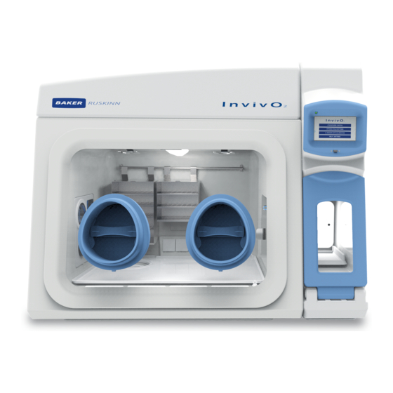
Baker InvivO2 400 User Manual
Physiological oxygen workstations
Hide thumbs
1
Table Of Contents
2
3
4
5
6
7
8
9
10
11
12
13
14
15
16
17
18
19
20
21
22
23
24
25
26
27
28
29
30
31
32
33
34
35
36
37
38
39
40
41
42
43
44
45
46
47
48
49
50
51
52
53
54
55
56
57
58
59
60
61
62
63
64
page
of
64
Go
/
64
Contents
Table of Contents
Troubleshooting
Bookmarks
Table of Contents
Table of Contents
Table of Figures
Introduction
Safety Instructions
Regulatory Compliance
European Region
North American Region
Precautions
Symbols
Table 1: List of Symbols
Transport and Storage
Location and Handling of the Invivo Workstation
Environmental Operating Conditions
Service Requirements
Electrical Supply Requirements
Figure 1: Invivo Rear Connections
Table 2: Electrical Service Requirements
Gas Supply Requirements
Figure 2: Gas Connection Graphic
Table 3: Fuse Ratings
Table 4: Standard Gases
Table 5: Additional Gases for Specific Operating Modes
Invivo 2 Overview
Front View
Figure 3: Standard Invivo Workstation with SPES Option
Figure 4: Large Invivo Workstation
Front Interior Views
Figure 5: Right Side Internal View
Figure 6: Left Side Internal View
Left Side View
Figure 7: Left Side End Panel with Ultrasonic Humidity Option
Right Side View
Figure 8: Right Side End Panel
Rear View
Figure 9: Rear End Panel and Supply Connections
Figure 10: Gas and Electrical Connections
Using the Workstation
Using the Interlock
Interlock Overview
Operating the Interlock Outer Door
Icon 1: Interlock Outer Door
Operating the Interlock Inner Door
Transferring Material into the Workstation Chamber Via the Interlock
Screen 1: Interlock Purge Options
Removing Material from the Workstation Chamber Via the Interlock
Hand Access to the Main Chamber
Figure 11: Ezee-Sleeves
Vacuum Operation
Figure 12: Compressed Ezee-Sleeve for Entry
Figure 13: Arm Inserted into Ezee-Sleeve (Shown with and Without Ezee-Sleeve)
Figure 14: Foot Pedals for Right and Left Glove Ports
Figure 15: Ezee-Sleeve before Vacuum
Figure 16: Ezee-Sleeve after Vacuum
Workstation Entry
Figure 17: Glove Port Cap
Figure 18: Glove Port Cap Stowage and Locator
Figure 19: Glove Port Cap Storage Location Inside Workstation
Workstation Exit
Figure 20: Glove Port Cap
Figure 21: Glove Port Locator
Humidity Control
Figure 22: Aquasorb Sachets - Empty and Charged
Figure 23: Aquasorb Sachet in Workstation
Figure 24: Humidity System Water Tank
Icon 2: Humidity Low Alarm
Figure 25: Water Tank Thumb Screw
Figure 26: Water Tank Lowered for Removal
Figure 27: Water Tank Tilted Forward Partially Removed
Figure 28: Water Tank Top Tube Removal
Figure 29: Water Tank Electrical Connector
Figure 30: Water Tank Bottom Lifted out
Figure 31: Water Tank Bottom Tube Disconnection
Figure 32: Condensate Plate
Figure 33: Condensate Output and Tray
Screens
Main Screen
Initial Settings Screen
Screen 4: Initial Settings Screen with Ultrasonic Humidity Option
Screen 5: Oxygen Level Set-Point Pop-Up
Table 6: Settings Screen Column Functions
Screen 6: Initial Settings Screen with Aquasorb Humidity Option
Environment Control
Screen 7: Environment Control Overview
Screen 8: Exit Gas Control Warning
Data Log
Screen 9: Trend Log
Utilities
Screen 10: Utilities Menu
Icon 3: Internal Lights Control
Hypoxic Cycle
Screen 11: Hypoxic Cycle Menu - Continuous Cycle on
Screen 12: Hypoxic Cycle Menu - Continuous Cycle off
Screen 13: Hypoxic Cycle Temperature and Humidity Settings
Oxygen Sensor Calibration
Screen 14: Oxygen Sensor Calibration
Help / Settings
Screen 15: Help / Settings Menu
Warnings
Screen 16: Temperature Alarm Screen
Screen 17: Water Tank Low Warning Screen
Screen 18: USB Memory Warning Screen
Screen 19: Gas MIX Time Limit Warning Screen
Screen 20: Input Gas Pressure Alarm
Table 7: Audible Alarm Sounds
Usb Trend Log
Table 8: Trend Log Data Fields
Cleaning and Service Requirements
Service and Cleaning Overview
Table 9: Cleaning and Service Details
Cleaning Procedure - During and after each Use
Cleaning Procedure - Deep Clean with Front Screens Removed
Figure 34: Front Screen Pneumatic Connector Disconnection
Icon 4: Front Screen Release
Year Service
Figure 35: Ceiling Panel Thumb Screws
Figure 36: Ceiling Panel Handle and Grab Catch
Figure 37: Large Detox Sachet
Figure 38: Gloveport Sleeves
Troubleshooting
The Workstation will Not Switch on
The Circuit Breaker Trips
Low Gas Pressure
Excessive Gas Usage
Internal Equipment Not Powering up
The Workstation Is Only Partially Operational
Warranty Information
Disposal Information
Contact Details
Advertisement
Quick Links
Download this manual
User Manual UM-037
InvivO
2
Physiological Oxygen Workstations
InvivO
400 / InvivO
500
2
2
Affix Serial Number Sticker Here
Table of
Contents
Previous
Page
Next
Page
1
2
3
4
5
Advertisement
Table of Contents
Need help?
Do you have a question about the InvivO2 400 and is the answer not in the manual?
Ask a question
Questions and answers
Related Manuals for Baker InvivO2 400
Oxygen Equipment Baker InvivO2 500 User Manual
Physiological oxygen workstations (64 pages)
This manual is also suitable for:
Invivo2 500
Table of Contents
Save PDF
Print
Rename the bookmark
Delete bookmark?
Delete from my manuals?
Login
Sign In
OR
Sign in with Facebook
Sign in with Google
Upload manual
Upload from disk
Upload from URL


Need help?
Do you have a question about the InvivO2 400 and is the answer not in the manual?
Questions and answers