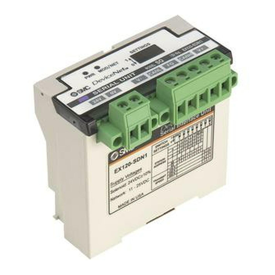
Summary of Contents for SMC Networks EX120-SDN1
- Page 1 Doc.No. EX## -OME0015 OPERATION MANUAL SI unit EX120-SDN1 EX121-SDN1 EX122-SDN1 EX124D/U-SDN1 SMC Corporation...
-
Page 2: Table Of Contents
Contents 1.Safety instructions 2.Specifications 2-1.General specifications 2-2.Electrical and network specifications ------------------------------------------------------ P4 2-3.Applicable solenoid valve series 3.Wiring and setting 3-1.Connection type 3-2.Address setting 4.LED indicator and Physical dimensions 4-1.LED indication 4-2.Physical dimensions 5.EDS(Electronic Data Sheet) File 6.Trouble Shooting ------------------------------------------------------ P3 ------------------------------------------------------ P4 ------------------------------------------------------ P5 ------------------------------------------------------ P5... -
Page 3: Safety Instructions
1.Safety instructions These safety instructions are intended to prevent a hazardous situation and/or equipment damage. These instructions indicate the level of potential hazard by label of "CAUTION" , "WARNING". To ensure safety, be sure to observe ISO, JIS and other safety practices. CAUTION: WARNING: CAUTION... -
Page 4: Specifications 2-1.General Specifications
2. Specifications 2-1. General specifications Item Model Operating ambient temp. Operating ambient humidity Storage ambient temp. Vibration proof Impact proof Noise immunity Withstand voltage Insulation resistance Operating environment Weight Protection class 2-2. Electrical and network specifications Item Applicable system Power supply voltage for communication Power supply voltage for solenoid valve Consumption Communication and... -
Page 5: 2-3.Applicable Solenoid Valve Series
SI unit I/O data (Receiving and sending data of polled command) Item Occupied byte Sending/ Address +0 receiving data Address +1 *) Mapping method of sending / receiving data is different by PLC. For further information, refer to the manual for PLC master (scanner) Bit of each output data and corresponding solenoid valve no. - Page 6 Cable specification Item Com m unication Signal Conductor 0.82 m m cross section Colors Blue, W hite 120Ω ± Im pedance 10% (1MHz) Propagation 1.36ns / ft(m ax) delay 500k:0.25dB / ft Attenuation 125k:0.13dB / ft rate 1.00M :0.40dB / ft Conductor 6.9Ω...
- Page 7 Wiring of cable for solenoid valve power supply and communication Communication connector for DeviceNet Terminal Wire color Connected to Black (-) side of power supply cable CANL Blue Low side of communication cable Ground / Shield CANH White High side of communication cable (+) side of power supply cable Power supply connector for solenoid valve Terminal...
-
Page 8: 3-2.Address Setting
3-2. Address setting Before setting of address by DIP switch, turn power supply for communication cable in SI unit “OFF”. Setting (binary) of following items is available by DIP switch installed to cover. 1) Node address (00 to 63) 2) Communication speed (125kbps, 250kbps, 500kbps) <Setting of node address>... -
Page 9: Led Indicator And Physical Dimensions
Green Lights up when power for DeviceNet line is supplied. Lights off Green flashing MOD / NET Green lights up flashing lights up 4-2 Physical dimensions SI unit (EX120-SDN1) SERIAL UNIT SERIAL UNIT SWITCH SWITCH SETTINGS SETTINGS STATION STATION ADDRESS... - Page 10 SI unit (EX121-SDN1) Flat cable length about 70mm Flat cable length about 70mm SERIAL UNIT SERIAL UNIT SWITCH SWITCH SETTINGS SETTINGS 2 2 3 3 4 4 5 5 6 6 7 7 8 8 1 1 2 2 4 4 8 8 16 16 32 32 STATION STATION ADDRESS...
- Page 11 SMC CORPORATION Doc.No.EX -OME0015 SI unit (EX124D-SDN1) SI unit (EX124U-SDN1) 4-G(PF)1/2 - 11 -...
-
Page 12: Eds(Electronic Data Sheet) File
* Please refer to the undermentioned list when DeviceNet controller or the scanner dose not automatically recognize the EDS File. $ Electronic Data Sheet File for $ SMC EX120-SDN1 Serial Interface Unit [File] DescText = "SMC EX120-SDN1 EDS File"; CreateDate = 05-20-1999;... -
Page 13: Trouble Shooting
6. Trouble Shooting MOD/NET LED Cause & Countermeasure Lights off PWR LED lights off <Countermeasure> Confirm that power for SI unit circuit is supplied. Confirm correct wiring. If above countermeasures do not improve status, please exchange SI unit. PWR LED lights up <Countermeasure>...


Need help?
Do you have a question about the EX120-SDN1 and is the answer not in the manual?
Questions and answers