
Subscribe to Our Youtube Channel
Related Manuals for IFR 2026

Summary of Contents for IFR 2026
- Page 1 MULTISOURCE GENERATOR 2026 Operating Manual Document part no. 46892/439 Issue 3 6 April 2001...
- Page 2 Option 4 − Rear-panel connections. This manual applies to instruments with software issues of 10.00 and higher. © IFR Ltd. 2007 No part of this book may be reproduced or transmitted in any form or by any means, electronic or mechanical,...
- Page 3 About this manual This manual explains how to use the 2026 Multisource Generator. Intended audience Persons who have a need for accurately generated signals in the VHF and UHF spectrum. It is assumed that the reader will be familiar with telecommunication terms used in modern communication systems.
- Page 4 Contents PREFACE ..............................iv Precautions ............................... v Précautions ..............................viii Vorsichtsmaßnahmen ............................x Precauzioni ..............................xii Precauciones ..............................xiv Chapter 1 GENERAL INFORMATION ....................1-1 Chapter 2 INSTALLATION ........................2-1 Chapter 3 LOCAL OPERATION......................3-1 First-time use ..........................3-9 Individual source operation....................3-17 Sweep ............................
- Page 5 PREFACE PATENT PROTECTION The 2026 Multisource Generator is protected by the following patents: EP 0322139 GB 2214012 US 4870384 EP 0125790 GB 2140232 US 4609881 46882/439...
- Page 6 Although the stored energy is within the approved safety requirements, a slight shock may be felt if the plug pins are touched immediately after removal. Do not remove covers, no user serviceable parts inside. See list of IFR Ltd International Service Centers at rear of manual.
- Page 7 PRECAUTIONS WARNING Fire hazard Make sure that only fuses of the correct rating and type are used for replacement. If an integrally fused plug is used on the supply lead, ensure that the fuse rating is commensurate with the with current requirements of this equipment. See under 'Performance Data' in Chapter 1 for power requirements.
- Page 8 This equipment has been designed and manufactured by IFR Ltd. to provide RF signals from two or three configurable sources. IFR Ltd. has no control over the use of this equipment and cannot be held responsible for events arising from its use other than for its intended purpose.
- Page 9 Ne pas enlever les capots, aucune pièce réparable ne se trouve à l'intérieur. Contacter un des Centres de Maintenance Internationaux de IFR Ltd dans la liste jointe à la fin du manuel. Fusibles Notez que le fusible d’alimentation interne est en série avec la phase du câble d’alimentation. Si la prise d’alimentation comporte deux bornes non polarisées, il est possible de connecter le fusible au...
- Page 10 PRECAUTIONS WARNING Risque lie au feu Lors du remplacement des fusibles vérifiez l'exactitude de leur type et de leur valeur. Si le cable d'alimentation comporte une prise avec fusible intégré, assurez vous que sa valeur est compatible avec les besoins en courant de l'appareil. Pour la consommation, reportez-vous au chapitre 1 "Spécifications".
- Page 11 Sicherheitsmargen liegt, kann ein leichter Spannungsschlag bei Berührung kurz nach der Unterbrechung erfolgen. Entfernen Sie keine Gehäuseabdeckungen, es befinden sich keine austauschbaren Teile im Gerät. Eine Liste der IFR Servicestellen finden Sie auf der Rückseite des Handbuches. Sicherungen Die interne Sicherung in der Spannungszuführung ist in Reihe mit der spannungsführenden Zuleitung geschaltet.
- Page 12 PRECAUTIONS WARNING Feuergefahr Es dürfen nur Ersatzsicherungen vom gleichen Typ mit den korrekten Spezifikationen entsprechend der Stromaufnahme des Gerätes verwendet werden. Siehe hierzu die Leistungsdaten (Performance Data) in Kapitel 1. WARNING Warnung vor giftigen Substanzen In einigen Bauelementen dieses Geräts können Epoxyharze oder andere Materialien enthalten sein, die im Brandfall giftige Gase erzeugen.
- Page 13 PRECAUTIONS Precauzioni Questi termini vengono utilizzati in questo manuale con significati specifici: WARNING riportano informazioni atte ad evitare possibili pericoli alla persona. riportano informazioni per evitare possibili pericoli all'apparecchiatura. riportano importanti informazioni di carattere generale. Simboli di pericolo Significato dei simboli di pericolo utilizzati nell'apparato: Simbolo Tipo di pericolo Pericolo generico...
- Page 14 PRECAUTIONS WARNING Pericolo d'incendio Assicurarsi che, in caso di sostituzione, vengano utilizzati solo fusibili della portata e del tipo prescritto. Se viene usata una spina con fusibili, assicurarsi che questi siano di portata adeguata coi requisiti di alimentazione richiesti dallo strumento. Tali requisiti sono riportati nel cap. 1 "Performance data".
- Page 15 PRECAUTIONS Precauciones Estos términos tienen significados específicos en este manual: WARNING contienen información referente a prevención de daños personales. contienen información referente a prevención de daños en equipos. contienen información general importante. Símbolos de peligro Los significados de los símbolos de peligro que aparecen en los equipos son los siguientes: Símbolo Naturaleza del peligro Peligro general...
- Page 16 PRECAUTIONS WARNING Peligro de incendio Asegúrese de utilizar sólo fusibles del tipo y valores especificados como recuesto. Si se utiliza una clavija con fusible incorporado, asegúrese de que los valores del fusible corresponden a los requeridos por el equipo. Ver sección de especificaciones del capítulo 1 para comprobar los requisitos de alimentación.
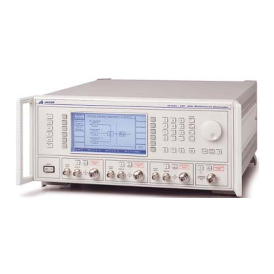
- Page 17 Versions, options and accessories....................1-9 Introduction The 2026 is a multisource signal generator offering as standard two signal sources in one instrument. Up to three sources may be fitted, each of which is a fully functional modulated signal generator. Each source can either be routed to its own individual RF output or switched to the input of an RF combiner network before being fed to a separate combined RF output.
- Page 18 GENERAL INFORMATION Main features Operation Selection of parameters on the screen may involve one or more of the numeric, hard or menu selection keys or the rotary control knob. Parameters may be set to specific values by numeric key entry, while values may be varied in steps of any size using the [ ][ ] keys or altered by moving the control knob, set to a particular sensitivity.
- Page 19 GENERAL INFORMATION Incrementing All major parameters can be incremented or decremented in step sizes entered via keyboard entry or remotely. If no step size is entered for a parameter, the steps are preset to 1 kHz for carrier frequency, 1 kHz for modulation oscillator, 1 kHz for FM deviation, 0.1% for AM depth, 0.01 rad for ΦM and 1 dB for output level.
- Page 20 GENERAL INFORMATION Performance data Carrier frequency Range: 10 kHz to 2.4 GHz with a resolution of 1 Hz. Accuracy: As frequency standard. RF output Range −137 dBm to +24 dBm Individual outputs: (output power above +20 dBm is uncalibrated for carrier frequencies above 1.2 GHz).
- Page 21 GENERAL INFORMATION VSWR For output levels less than −5 dBm, output VSWR is less than 1.5:1 for Individual outputs: carrier frequencies up to 1.2 GHz and less than 1.7:1 up to 2.4 GHz. Combined output: Output VSWR is less than 1.22:1 for carrier frequencies between 1 MHz and 1.2 GHz, and less than 1.32:1 up to 2.4 GHz.
- Page 22 GENERAL INFORMATION Modulation FM, AM or phase modulation can be applied to the carriers generated by each signal source from independent internal or external modulation sources. The internal modulation sources are capable of generating two simultaneous signals into any one of the modulation channels.
- Page 23 GENERAL INFORMATION ΦM on AM: Typically 0.1 radian at 30% depth at 470 MHz. *For RF levels not exceeding +10 dBm (individual output) or −4 dBm (combined output). Pulse modulation Carrier frequency range: 32 MHz to 2.4 GHz, usable to 10 MHz. RF level range: Maximum guaranteed output is reduced by 5 dB when pulse modulation is selected.
- Page 24 GENERAL INFORMATION All signal source parameters except the supply switch are remotely RS-232: programmable. Connector: 9-way male D-type Baud rate: 300 to 9600 bit/s. Handshake: Hardware: DTR, RTS, CTS and DSR. Software: XON and XOFF. Electrical interface: Interface to EIA-232-D. Conforms with the protection requirements of Council Directive Electromagnetic compatibility 89/336/EEC.
- Page 25 GENERAL INFORMATION Versions, options and accessories When ordering please quote the full ordering number information. Ordering numbers Versions 2026 10 kHz to 2.4 GHz MultiSource Generator with two signal sources. Options Option 1 Three internal signal sources. Option 3 High-stability frequency standard.
- Page 27 GENERAL INFORMATION 46882/439 1-11...
-
Page 28: Table Of Contents
Chapter 2 INSTALLATION Contents Mounting arrangements ......................... 2-2 Installation requirements........................ 2-2 Ventilation ..........................2-2 Class I power cords......................... 2-2 Goods-in checks..........................2-5 Connecting to supply ........................2-5 Fuse............................2-5 General purpose interface bus (GPIB) ................... 2-5 GPIB cable connection ......................2-5 GPIB connector contact assignments.................. -
Page 29: Mounting Arrangements
In the event that a molded plug has to be removed from a lead, it must be disposed of immediately. A plug with bare flexible cords is hazardous if engaged in a live socket outlet. Power cords with the following terminations are available from IFR Ltd. Please check with your local sales office for availability. - Page 30 Failure to ground the equipment may expose the operator to hazardous voltage levels. Depending upon the destination country, the color coding of the wires will differ: Wire ended Country IEC 320 plug type IFR part number GREEN/YELLOW EARTH Universal Straight through...
- Page 31 INSTALLATION Français Le câble d’alimentation d’Europe Continentale est muni d’un connecteur mâle à angle droit type CEI83, standard C4 (CEE 7/7), qui peut être utilisé dans une prise femelle à ergot de terre (standard C 3b) ou à clips latéraux (standard C 2b), cette dernière étant communément appelée prise “Schuko”...
-
Page 32: Goods-In Checks
INSTALLATION Goods-in checks The following goods-in check verifies that the instrument is functioning correctly, but does not verify conformance to the listed specification. To verify that the instrument conforms to the specification given in Chapter 1, refer to Chapter 7, ‘Acceptance testing’. (1) Ensure that the correct fuse is fitted (accessible from the rear panel) and connect the instrument to the supply. -
Page 33: Gpib Connector Contact Assignments
INSTALLATION GPIB connector contact assignments The contact assignments of the GPIB cable connector are as given in the table below and shown in Fig. 2-1. Contact Function Contact Function Data I/O 1 DataI/O 5 Data I/O 2 DataI/O 6 Data I/O 3 DataI/O 7 Data I/O 4 DataI/O 8... -
Page 34: Interface Bus Connection
Clear to send Ring indicator The RS-232 interface can be connected to a personal computer’s AT connector using a null-modem cable. A suitable cable is available from IFR − see Chapter 1, ‘Versions, options and accessories’. Auxiliary port connector The rear-panel 25-way female D-type AUXILIARY PORT connector is shown in Fig. -
Page 35: Fsk Operation
INSTALLATION FSK operation Data for FSK operation is carried on the contacts of the AUXILIARY PORT as shown by Table 2-1 below. The unused contacts are left unconnected. Table 2-1 Auxiliary port contact assignments CONTACT FUNCTION Source A − FSK A Source A −... -
Page 36: Rack Mounting
INSTALLATION Rack mounting The instrument, which is normally supplied for bench mounting, may be mounted in a standard 19 inch rack (see Chapter 1, ‘Versions, options and accessories’). There are two slide rack mounting kits to accommodate different depths of cabinet. These kits include full fitting instructions. -
Page 37: Cleaning The Lcd Window
The above information is provided for guidance only. IFR Ltd designs and constructs its products in accordance with International Safety Standards such that in normal use they represent no hazard to the operator. IFR Ltd reserves the right to amend the above information in the course of its continuing commitment to product safety. - Page 38 Chapter 3 LOCAL OPERATION Contents Introduction............................ 3-4 Conventions ........................... 3-4 Front-panel controls and connectors ....................3-4 Rear-panel connectors........................3-6 First-time use..........................3-9 Switching on ..........................3-9 Display ............................3-9 Selecting functions and keyboard entry ..................3-12 Parameter adjustment........................3-13 Displaying shifts .......................... 3-14 Combiner summary........................
- Page 39 Fig. 3-1 2026 front panel ......................3-4 Fig. 3-2 2026 rear panel ......................3-6 Fig. 3-3 2026 Sig Gen menu in normal operation showing default display........3-9 Fig. 3-4 Division of the Sig Gen menu (main display) into fields ..........3-11 Fig. 3-5 Steps menu ........................3-14 Fig.
- Page 40 LOCAL OPERATION Fig. 3-31 Lock and unlock utility (during password entry) ............3-38 Fig. 3-32 Utilities selection menu 2 .................... 3-39 Fig. 3-33 Software status display....................3-39 Fig. 3-34 Hardware status display ....................3-40 Fig. 3-35 Patent information display................... 3-40 Fig.
- Page 41 The numerical keys are used to set parameters to specific values which can also be varied in steps of any size by using the [ ][ ] keys or the rotary control knob. Fig. 3 1 2026 front panel 46882/439...
- Page 42 LOCAL OPERATION SUPPLY Switches the AC supply voltage on and off. [A], [B], [C] This key is repeated for each signal source. It selects A, B or C as the current signal source for parameter display and adjustment. The C source is optional. [SETUP] Displays the Setup Menu used for signal source configuration and for selecting an application mode..
- Page 43 LOCAL OPERATION Rear-panel connectors The rear-panel connectors are shown in Fig. 3 2 below. Fig. 3 2 2026 rear panel COMBINED RF An Option 4 50 Ω type OUTPUT (optional) N connector. When fitted, replaces the front-panel connector. PULSE INPUT An Option 4 10 kΩ...
- Page 44 LOCAL OPERATION AUXILIARY PORT pin socket. Can accept external data to modulate each of the internal sources for 2 level or 4 level FSK. For contact allocation see ‘Auxiliary port connector’ in Chapter 2. 50 Ω SMA connector. Enables a signal to be fed into the EXT I/P combiner from an external signal generator.
- Page 46 A source. B3420 Fig. 3-3 2026 Sig Gen menu in normal operation showing default display Display Before entering any parameters it will be found useful to look at the effect that pressing various keys has on the display for the Sig Gen menu.
- Page 47 LOCAL OPERATION on the screen apply to that source; for example, when the A panel is highlighted, the displayed carrier frequency, RF level, modulation etc., apply only to the A source. The selected signal source can be changed using the [A], [B] and [C] hard keys. The RF output from a source may be directed to its own output socket, or re routed via the combiner (either alone or in combination with other sources) to the combiner output socket.
- Page 48 FIRST TIME USE Carrier frequency RF level Frequency standard Modulation state Soft Soft keys keys Modulation Error message Signal source C3290 Fig. 3 4 Division of the Sig Gen menu (main display) into fields Modulation field This field shows all the current modulation settings for the selected signal source: type of modulation;...
- Page 49 LOCAL OPERATION Error message field Error messages are displayed here when, for example, you exceed a parameter limit. A list of error messages is given at the end of this chapter. Soft key fields These fields can hold up to 12 soft key labels. Some soft keys are used to select a field for data entry (e.g.
- Page 50 FIRST TIME USE at 100 kHz deviation, sine wave modulated at 500 Hz from the A source RF OUTPUT socket. Parameter adjustment When a function has been selected, you can increment or decrement its parameter either continuously using the control knob or in steps using the [ ] and [ ] keys. You can also simultaneously adjust two parameters by means of the [KNOB LOCK] key.
- Page 51 LOCAL OPERATION Using the steps keys The selected function’s parameter may be adjusted in steps using the [ ] and [ ] keys to respectively increment and decrement the parameter. The step size can be set as follows: (1) Press the [SET Δ] key which causes the Steps Menu to be displayed (see Fig. 3-5 below). This shows the step sizes of the currently selected signal source.
-
Page 52: Combiner Summary
FIRST TIME USE B3422 Fig. 3-6 Total shift menu (2) Carrier frequency and RF level, as well as modulation depth/deviation and frequency − in ϕ M] keys − can be further adjusted using the combination with the [AM], [FM] and [ appropriate [Shift] key. -
Page 54: Individual Source Operation
Individual source operation The following section describes the method of controlling the settings of the individual signal sources. The method of control can be used irrespective of the routing of the signal source output, whether to its own RF OUTPUT or to the COMBINED RF OUTPUT, and irrespective of any coupling that may have been set up. -
Page 55: Carrier On/Off
LOCAL OPERATION Carrier on/off The carrier can be switched on or off at any time by means of the [RF ON/OFF] key. This effectively switches the output on and off, retaining the 50 Ω output impedance. RF level selection − You can enter the RF level in the range 137 to +24 dBm (to +20 dBm above 1.2 GHz). -
Page 56: Modulation Selection
INDIVIDUAL SOURCE OPERATION The protection circuit can be reset by pressing the [RPP Reset] key for the appropriate source after having either removed the signal to the source or terminated the RF OUTPUT socket. The display then returns to the menu in use at the time that the RPP was tripped. If [RPP Reset] is pressed with the signal still applied, the RPP will trip again. -
Page 57: Sig Gen Screens
LOCAL OPERATION (2) Use the [Up] and [Down] keys to move the selection box over the required modulation mode. Repeated pressing of the [Down] key will cause the screen to scroll, revealing further selections. (3) Press [Select Mode]. The display changes to show your new current modulation mode. (4) Press [SIG GEN] to display the Sig Gen menu which has been modified to show the new configuration. -
Page 58: Internal Waveform Selection
INDIVIDUAL SOURCE OPERATION Internal waveform selection Having selected an internal modulation mode, you can select the type of waveform as follows: (1) Press [SIG GEN] to show the Sig Gen menu. (2) Press [Select Waveform] to display the Internal Source Waveform Menu. This shows the currently selected modulation and waveform (see Fig. -
Page 59: External Source Coupling
LOCAL OPERATION (7) Press [Phase Diff] and adjust the phase using the control knob. Turn clockwise to advance the phase and anticlockwise to retard the phase. Note that if you have set the source phase and subsequently adjusted the source frequency or changed the waveform, the menu Phase Difference: value will be blanked. -
Page 60: Modulation On/Off
INDIVIDUAL SOURCE OPERATION Modulation ON/OFF [Mod ON/OFF] switches all modulation ON or OFF and the condition is indicated in the centre of the Sig Gen menu: Modulation DISABLED Modulation is also controlled by the individual modulation ON/OFF keys. For modulation to appear on the carrier, modulation must be both enabled with the [Mod ON/OFF] key and the ϕ... -
Page 61: Frequency Modulation Selection
LOCAL OPERATION Frequency modulation selection Select frequency modulation as follows: (1) Press [SIG GEN] to show the Sig Gen menu with the current modulation displayed in the bottom half of the screen. (2) Press the [FM] soft key if displayed (otherwise the instrument is already in the FM mode). (3) Press [FM Devn]. -
Page 62: Fsk Selection
INDIVIDUAL SOURCE OPERATION (5) Press [Pulse ON/OFF] to toggle between the ON and OFF states until the display shows Pulse ON. When ON the carrier is controlled by the logic level applied to the PULSE INPUT socket. A logical ‘1’ (a voltage between 3.5 and 5 V) allows carrier output, a logical ‘0’ (a voltage between 0 and 1.0 V) suppresses it. -
Page 64: Sweep
Sweep The sweep capability allows the comprehensive testing of systems, since measurements at single points will not necessarily give an overall indication of the performance. The sweep function is specified by the following parameters: • Start frequency • Stop frequency •... -
Page 65: Sweep Control
LOCAL OPERATION (3) Select the A, B or C source for sweeping by pressing the appropriate [A Swept Source], [B Swept Source] or [C Swept Source] key. (4) Select the sweep mode between single shot and continuous sweeping by pressing the [Sweep] key which toggles between [Single Sweep] and [Cont Sweep]. - Page 66 SWEEP (14) Whilst the sweep is paused you can adjust the frequency by selecting [Sweep Freq] then using the control knob to look at a particular frequency of interest. Pressing [Transfer] followed by [Continue Sweep] causes the sweep to continue from your adjusted frequency. Otherwise simply pressing [Continue Sweep] restarts the sweep from where it was paused.
-
Page 68: Utilities
Utilities Utility menu selection Pressing the [UTIL] key gains access to the utilities options from two primary menus, Utilities Selection Menu 1 and Utilities Selection Menu 2. When a selection is made from either of these menus and [UTIL] is subsequently pressed, the primary menu is re-displayed. However, if instead a selection is made and then one of the other hard keys −... -
Page 69: Frequency Standard Selection (Menu 1)
LOCAL OPERATION B3454 Fig. 3-22 Display adjustment utility (2) Set the required brightness by pressing [Dim], [Medium] or [Bright]. You can then adjust the contrast by means of the control knob. (3) Once adjusted, the display setting can be stored in the non-volatile memory by pressing [Save LCD Setting]. -
Page 70: Carrier Phase Adjustment (Menu 1)
UTILITIES [10 MHz Ext Dir] if your provided 10 MHz standard is better than that fitted in the instrument. (4) To obtain an internally generated 10 MHz standard from the instrument’s INT STD O/P socket, select [10 MHz Int Out]. (5) Press [EXIT] to return to the Utilities Selection Menu 1. -
Page 71: Ω /75 Ω Impedance Selection (Menu 1)
LOCAL OPERATION B3457 Fig. 3-25 RF level units selection menu (2) Select between linear and logarithmic units in EMF or PD. Logarithmic units may be referred to volts (dBV), millivolts (dBmV), microvolts (dBμV) or to 1 millivolt into 50 Ω (dBm). -
Page 72: Power-Up Options (Menu 1)
UTILITIES Power-up options (menu 1) The instrument can power-up in one of two states; with the factory settings or with the settings of your choice stored in one of the full memory locations. Selection is made as follows: (1) Press [Power Up Options] to display the Power Up Options Menu shown in Fig. 3-27 below. This shows the currently selected power-up choice. -
Page 73: Modulation Mode Selection (Menu 1)
LOCAL OPERATION Table 3-1 Instrument default settings Source selected Source A Carrier frequency (Maximum available) 2.4 GHz Step : 1 kHz −137 dBm RF level Step : 1 dB Status: ON Modulation mode Internal FM, modulation disabled Modulations Deviation: 0 Hz, OFF Internal source, frequency: 1 kHz, sine Deviation: 0 Hz, OFF Internal source, frequency: 400 Hz, sine... -
Page 74: Remote Control Selection (Menu 1)
UTILITIES Remote control selection (menu 1) The remote mode of operation is selected as follows: (1) Select [Remote Control] to display the Remote Control Utility. This shows the currently selected remote mode (see Fig. 3-29 below). B3475 Fig. 3-29 Remote control utility (2) Press [GPIB/RS232] to toggle between GPIB and RS232. -
Page 75: Protection Locking And Unlocking (Menu 1)
LOCAL OPERATION B3476 Fig. 3-30 Current background errors display (showing example errors) (2) Where there are more background errors than can be displayed on one screen page, the [Next Page] and [Previous Page] soft keys will be displayed to enable more than one page of errors to be viewed. -
Page 76: Selection Menu 2
UTILITIES (6) Press [EXIT] to return to the Utilities Selection Menu 1. If you have lost or forgotten the password contact our Customer Services or your nearest agent (for addresses see inside rear cover). You will be required to give the instrument’s serial number. -
Page 77: Hardware Information (Menu 2)
LOCAL OPERATION Hardware information (menu 2) You can obtain a description of the instrument’s hardware by pressing [Hardware Status] which causes Fig. 3-34 below to be displayed. This shows the instrument type and serial number as well as options fitted. B3479 Fig. -
Page 78: Latch Access Utility (Menu 2)
UTILITIES B3481 Fig. 3-36 Display blanking utility (1) Unlock the protection to Level 1 by means of the Lock & Unlock Utility (menu 1). (2) Press [Display Blanking] which causes the screen shown in Fig. 3-36 above to be displayed. (3) To blank the screen press the [Blanking ON/OFF] key which toggles between the on and off states. -
Page 79: Rpp Trip Count Utility (Menu 2)
LOCAL OPERATION B3516 Fig. 3-38 Elapsed time utility RPP trip count utility (menu 2) This utility lists the number of times each of the fitted sources has tripped. The screen is shown in Fig. 3-39 below. B3526 Fig. 3-39 RPP trip count utility Display test utility (menu 2) This utility provides a simple test of the display. -
Page 80: Key/Knob Tests (Menu 2)
UTILITIES Key/knob tests (menu 2) In this utility the user is invited to operate the keys and control knob whilst checking the reaction of the instrument. The screen is shown in Fig. 3-41 below. B3528 Fig. 3-41 Keyboard/knob test utility Calibration utility (menu 2) This menu shows when each individual item was last adjusted and enables you to enter the date of the current adjustment. -
Page 82: Memory
Memory Memory stores There are three types of store: carrier, full and RAM. Both carrier and full stores are non-volatile. The contents of the RAM store are lost when the instrument is switched off. Each type of store holds the data for all fitted sources. Carrier store The non-volatile carrier frequency store has 100 locations numbered 0 to 99 for the storage of carrier frequency only. -
Page 83: Storing Data
LOCAL OPERATION Storing data Select the memory store function as follows: (1) Press the [MEM] hard key and then, if necessary, press the [Store/Recall] soft key to display the Memory Store Menu shown in Fig. 3-43 below. B3482 Fig. 3-43 Memory store menu (2) To store data, press the [Full Store], [Carrier Store] or [RAM Store] key for the type of store required, then enter the store location via the numerical key pad and terminate with [ENTER]. -
Page 84: Memory Protection Menu
MEMORY (3) Press [EXIT] to return to the Memory Store Menu. Memory protection menu (4) To change the write protection, the instrument must be unlocked to Level 1 (see ‘Protection locking and unlocking’ on page 3-38). Subsequently pressing [Memory Protect] causes the Memory Write Protection Menu similar to that shown in Fig. -
Page 85: Recalling Data
LOCAL OPERATION Recalling data Select the memory recall function as follows: (1) Press the [MEM] hard key and then, if necessary, press the [Store/Recall] soft key to display the Memory Recall Menu shown in Fig. 3-46 below. B3485 Fig. 3-46 Memory recall menu (2) To recall data, press the [Full Store], [Carrier Store] or [RAM Store] key for the type of recall required, then enter the store location via the numerical key pad and terminate with [ENTER]. -
Page 86: Error Messages
Error messages Error handling Error messages are divided into four groups: − represent a condition of the instrument. Background errors − generally caused by the user. Foreground errors − generated by incorrect programming. GPIB errors − caused by failure associated with the main RAM or the Fatal errors PROM. -
Page 87: Source-Specific Errors
LOCAL OPERATION Source-specific errors Where it is necessary to identify the signal source causing an error, the error message number has 1000, 2000 or 3000 added to it for the A, B and C sources respectively. Thus error number 2500 indicates that the B source has tripped the reverse power protection circuit. - Page 88 ERROR MESSAGES Table 3-3 Foreground errors (0−399) No error EEPROM checksum ‡ ‡ Pad cal checksum RF cal checksum ‡ ‡ Freq std checksum Synthesizer cal checksum ‡ ‡ Mod ref checksum Mod offset checksum ‡ ‡ Mod amp checksum ALC cal checksum ‡...
- Page 89 LOCAL OPERATION Foreground errors (0−399) - continued Transmit buffer full Receiver not enabled Protected utility − Level 1 Protected utility − Level 2 − − This store is Read Only − − − − ‡ Receive buffer full Pulse has been disabled No attenuator fitted No high power amp fitted −...
- Page 90 ERROR MESSAGES − Table 3-4 GPIB errors (400 499) Syntax error Unrecognized mnemonic Numeric syntax Data expected Illegal data Too much data Incorrect data type Unrecognized character data Character data not unique Block definition Block size Missing quote Terminator expected Invalid unit Unit not expected No header match found...
- Page 91 Chapter 4 SETUP Contents Summary ............................4-2 Setup menu selection ........................4-2 Combiner setup ..........................4-3 Combiner selection ........................4-3 External source ........................4-4 Coupling............................4-5 Frequency and level coupling ......................4-5 Coupling selection ........................4-5 Applications ..........................4-7 Applications summary ........................4-7 Applications selection ........................
-
Page 92: Summary
SETUP Summary The setup menus are used to route the outputs from the signal sources to either their individual RF OUTPUT sockets or, via the combiner, to the COMBINER RF OUTPUT socket and additionally allow the sources to be coupled together by a mathematical formula in both frequency and level. The routing is set using the combiner setup facility and the coupling parameters are enabled and set using the coupling setup facility. -
Page 93: Combiner Setup
Combiner setup This facility allows the user to route an individual signal source (A, B or C) to either its designated separate RF OUTPUT connector or through the combiner to the COMBINED RF OUTPUT connector. The current routing of the signal sources is always indicated by the source field at the bottom of the display. -
Page 94: External Source
SETUP External source Provision is made on the rear panel for connecting an external signal generator to the combiner via the EXT I/P connector. For a generator fitted with three internal sources an additional connector, INT O/P, is fitted. The EXT I/P and INT O/P sockets effectively interrupt the C output to the combiner. -
Page 95: Coupling
Coupling Frequency and level coupling Many measurements are made where it is convenient if the carrier frequencies and RF levels of signal sources are automatically related to each other. The coupling setup facility allows two or more signal sources to be coupled together in frequency and/or level. The frequencies can be coupled with a defined offset value (for example, 10.7 MHz), and can be harmonically related. - Page 96 SETUP Frequency (2) Select the required source by toggling between the [A & B Coupling] and [A & C Coupling] keys. (3) Select [Freq Offset] and enter the required offset from the A source, positive or negative, up to the instrument’s maximum frequency and terminate with the [Hz], [kHz], [MHz] or [GHz] key.
-
Page 97: Applications
Applications Applications summary The 2026 Multisource Generator supports a number of measurement applications which require more than one signal source to be coupled together. In addition to automatically selecting the most appropriate signal routing format, the applications mode also automatically couples the sources together and modifies the descriptions of the parameters entered to best suit the application. -
Page 98: Amplifier Intermodulation Distortion Application
In the 2026 the peak levels can be identified by phase (or frequency) modulating source C and using a peak hold on the measuring instrument. Alternatively, the phase of source C can be adjusted (with no modulation applied) until a peak response is found. - Page 99 APPLICATIONS (3) Press [Spectral Diagram] which displays the Intermod. Distortion Test on Amplifier spectral diagram as shown in Fig. 4-7 below. B3391 Fig. 4-7 Intermod. distortion test on amplifier spectral diagram (4) The spectral diagram shows the default setting with the B source offset higher in frequency than the A source (for a 2-tone test) and the C source offset lower in frequency than the A source (for a 3-tone test).
- Page 100 SETUP (10) When you select 3 Tone four additional soft keys are displayed as shown in Fig. 4-9 below. B3393 Fig. 4-9 Intermod. distortion test on amplifier: 3-tone selected (11) For 3-tone operation press the [Mod’n Mode] key to access the Modulation Setup Menu shown in Fig.
- Page 101 APPLICATIONS B3395 Fig. 4-11 Intermod. distortion test on amplifier: Source summary screen (16) At the conclusion of the test, press [EXIT] to return to the previous screen to continue with the application. (17) To choose another application or to cancel the current application and return to normal operation, press [SETUP].
-
Page 102: Receiver Two-Tone Intermodulation Application
SETUP Receiver two-tone intermodulation application When a receiver is demodulating a low level input signal, it is possible for two-high level out-of-band signals to generate intermodulation products in the receiver which interfere with the wanted signal. Receivers have to be tested for their susceptibility to such signals to ensure that the communication system is robust in adverse conditions. - Page 103 APPLICATIONS (4) The spectral diagram shows the default setting with the A source set to the receiver channel, the B source (interferer 1) offset higher in frequency than the A source, and the C source (interferer 2) set to twice that offset. You can reverse the positions of the B and C sources with respect to A so that the A source is at the higher frequency by entering a negative offset.
- Page 104 SETUP (10) Select [Offset Freq] to change the equidistant offsets of the B and C sources. You can reverse the relative positions of the B and C sources with respect to A by entering a negative offset frequency. (11) Set the interference ratio between the A source input level and the B and C source input levels by pressing [Interf Ratio] and entering the ratio in dB.
-
Page 105: Receiver Selectivity Application
APPLICATIONS displayed. The screen is split horizontally in two, with the upper part displaying the application mode and the lower part displaying the application cancellation selection. B3403 Fig. 4-19 Setup menu in application mode (18) To choose another application press [Appl’n Menu] which returns you to the Applications Selection Menu. - Page 106 SETUP (3) Press [Spectral Diagram] which displays the Receiver Selectivity spectral diagram as shown in Fig. 4-21 below. B3405 Fig. 4-21 Receiver selectivity spectral diagram (4) As shown by the spectral diagram, the A source is set to the receiver channel and the B source is offset higher in frequency than the A source at a multiple of the channel spacing.
- Page 107 APPLICATIONS B3407 Fig. 4-23 Receiver selectivity: receiver modulation setup menu (9) When the A source is modulated press [Rx Mod’n ON/OFF] to toggle between the two states as shown by the screen. (10) If you want to apply modulation to the interferer (B source) press the [Interf Mod’n] key to access the Interferer Modulation Setup Menu shown in Fig.
- Page 108 SETUP B3409 Fig. 4-25 Receiver selectivity: source summary (18) At the conclusion of the test, press [EXIT] to return to the previous screen to continue with the application. (19) To choose another application or to cancel the current application and return to normal operation, press [SETUP].
- Page 109 Chapter 5 REMOTE OPERATION Contents Preparing the instrument for remote operation ................5-2 Introduction..........................5-2 Local lockout .......................... 5-2 Remote/local operation ......................5-2 Remote operation selection......................5-2 RS-232 operation ........................... 5-3 RS-232 control port ........................ 5-3 Handshaking ........................... 5-3 Control characters ........................5-3 Setting RS-232 parameters .....................
-
Page 110: Preparing The Instrument For Remote Operation
Preparing the instrument for remote operation Introduction The 2026 MultiSource Generator can be controlled remotely using either the RS - 232 interface or the GPIB (General Purpose Interface Bus) interface. The command set used is designed to comply with IEEE 488.2. In RS - 232 mode some IEEE 488.2 features are not implemented due to the restrictions of the interface. -
Page 111: Rs-232 Operation
REMOTE OPERATION RS-232 operation RS-232 control port The connections required between the RS-232 serial port and the controlling device are described in Chapter 2 under ‘RS-232 interface’. Handshaking Software only Flow control is achieved by XON/XOFF. All control lines are normally in the OFF state and are ignored. Hardware only Flow control is achieved DSR or CTS to suspend transmission from the instrument and using DTR to suspend transmission from the controller. -
Page 112: Gpib Operation
(1) Press [GPIB Address] and enter the address which must be unique on the system to the instrument and within the range 0 to 30. GPIB functions The IEEE 488.1 interface functions offered by the 2026 MultiSource Generator are as follows: Source handshake (SH1) complete capability. -
Page 113: Device Listening Elements
REMOTE OPERATION Device listening elements The following is a list of the device listening elements (as defined in the IEEE 488.2 standard) which are used in the instrument: <PROGRAM MESSAGE> <PROGRAM MESSAGE TERMINATOR> <PROGRAM MESSAGE UNIT> <PROGRAM MESSAGE UNIT SEPARATOR> <COMMAND MESSAGE UNIT>... -
Page 114: Programming
REMOTE OPERATION Programming Program messages A message consists of one or more message units. Message units are separated by a semi-colon (;). The whole message is ended by the Program Message Terminator (or End Of Message) defined as one of the following: <newline>... -
Page 115: Program Data
REMOTE OPERATION Program data Data can take many forms, as follows: Decimal Numeric Data is a flexible numeric format which encompasses integer, fixed point and floating point (mantissa and exponent) representations. Data is rounded to a resolution appropriate to the function. Decimal data can, in most cases, be followed by the appropriate units. - Page 116 <manufacturer>,<model>,<serial number>,<software part number and issue number>. where: <manufacturer> is IFR, <model> is the instrument model number, which is 2026. <serial number> is the instrument serial number in the form nnnnnn/nnn, where n is an ASCII digit in the range 0 to 9.
-
Page 117: Device-Dependent Commands
REMOTE OPERATION Device-dependent commands The following list describes the features of the device-dependent mnemonics for the instrument together with simple examples of their use within each major section (Carrier frequency, RF level, etc.) The root mnemonic is listed first followed by the lower level mnemonics. Each group is followed by a list of requirements for data type and suffix. -
Page 118: Source Selection
REMOTE OPERATION Source selection SOURCE Select RF Source A, B or C as current source. When a source is selected, the source-specific commands and queries will then apply to that source. Data type : Character Program Data (A, B or C) Allowed suffices : None Default suffix :... - Page 119 REMOTE OPERATION Allowed suffices : None Default suffix : None :HARM Set Harmonic for carrier frequency coupling relationship :SUBHARM Set Sub-harmonic for carrier frequency coupling relationship Data type : Decimal Numeric Program Data Allowed suffices : None Default suffix : None :OFFSET Set Frequency Offset for carrier frequency coupling relationship...
-
Page 120: Carrier Frequency (Source-Specific)
REMOTE OPERATION Carrier frequency (source-specific) CFRQ Set Carrier Frequency (short form) :VALUE Set Carrier Frequency :INC Set Carrier Frequency step Data type : Decimal Numeric Program Data Allowed suffices : Any one of: GHZ, MHZ, KHZ or HZ Default suffix : Go UP one step Go DOWN one step :RETN... -
Page 121: Rf Level (Source-Specific)
REMOTE OPERATION RF level (source-specific) RFLV Set RF Output Level (short form) :VALUE Set RF Output Level Data type : Decimal Numeric Program Data Allowed suffices : Any one of: DBM, DBV, DBMV, DBUV, V, MV, UV OR NV. Default suffix : DBM unless changed by UNITS command :INC Set RF Level step (dB) -
Page 122: Modulation Mode (Source-Specific)
REMOTE OPERATION Modulation mode (source-specific) MODE Set modulation mode Data type : Character Program Data (valid combinations of AM, FM, PM, FSK2L, FSK4L or PULSE. See table below.) Allowed suffices : None Default suffix : None Examples: MODE AM,FM MODE FM,PULSE VALID MODE COMBINATIONS TABLE AM [,PULSE] FM [,PULSE]... -
Page 123: Frequency Modulation (And Fsk) (Source-Specific)
REMOTE OPERATION Frequency modulation (and FSK) (source-specific) FM or FM1 or FM2 Set FM Deviation (short form) :DEVN Set FM Deviation :INC Set FM step size Data type : Decimal Numeric Program Data Allowed suffices : Any one of: GHZ, MHZ, KHZ or HZ Default suffix : :<src>... - Page 124 REMOTE OPERATION DCFMNL Perform DC FM null operation Data type : None Allowed suffices : None Default suffix : None Example: DCFMNL Prepares message containing information on FM setting in one of the FM? or FM1? or FM2? following formats: :FM:DEVN <nr2>;<src>;<status>;INC <nr2>...
-
Page 125: Phase Modulation (Source-Specific)
REMOTE OPERATION Phase modulation (source-specific) PM or PM1 or PM2 Set Phase Modulation Deviation (short form) :DEVN Set Phase Modulation Deviation Set Phase Modulation step size :INC Data type : Decimal Numeric Program Data Allowed suffices : Default suffix : :<src>... - Page 126 REMOTE OPERATION PM:MODF? or PM1:MODF? Prepares message containing information on PM modulation oscillator setting or PM2:MODF? in one of the following formats: :PM:MODF:VALUE <nr2>;<shape>;INC <nr2> :PM1:MODF:VALUE <nr2>;<shape>;INC <nr2> :PM2:MODF:VALUE <nr2>;<shape>;INC <nr2> where: <shape> is a program mnemonic representing the waveform shape Example: :PM2:MODF:VALUE 2500.00;TRI;INC 500.00...
-
Page 127: Amplitude Modulation (Source-Specific)
REMOTE OPERATION Amplitude modulation (source-specific) AM or AM1 or AM2 Set AM Depth (short form) Set AM Depth :DEPTH Set AM step size :INC Data type : Decimal Numeric Program Data Allowed suffices : Default suffix : :<src> Select modulation source where <src> is any one of: INT, EXTAC, EXTALC, or EXTDC Turn AM ON (locally) Turn AM OFF (locally) - Page 128 REMOTE OPERATION AM? or AM1? or AM2? Prepares message containing information on Amplitude Modulation setting in one of the following formats: :AM:DEPTH <nr2>;<src>;<status>;INC <nr2> :AM1:DEPTH <nr2>;<src>;<status>;INC <nr2> :AM2:DEPTH <nr2>;<src>;<status>;INC <nr2> where <src> is a program mnemonic representing the source of the modulation signal and <status>...
-
Page 129: Pulse Modulation (Source-Specific)
REMOTE OPERATION Pulse modulation (source-specific) PULSE [not used alone] Turn Pulse modulation ON Turn Pulse modulation OFF :OFF Data type : None Allowed suffices : None Default suffix : None Examples: PULSE:ON PULSE:OFF Prepares message containing information on Pulse Modulation setting in the PULSE? following format: :PULSE:<status>... -
Page 130: Memory − Store
REMOTE OPERATION Memory − store [not used alone] Carrier Freq Store 0−99 :CFRQ Full Store 0−99 :FULL RAM Store 0−99 :RAM Data type : Decimal Numeric Program Data Allowed suffices : None Default suffix : None Examples: STO:FULL 45 STO:CFRQ 16 Memory −... -
Page 131: Memory − Protection
REMOTE OPERATION Memory − protection MPROT [not used alone] [not used alone] :CFRQ Set the start of the Carrier Freq Stores memory block which is to be :START protected/unprotected. Set the end of the Carrier Freq Stores memory block which is to be :STOP protected/unprotected. -
Page 132: Sweep Operation
REMOTE OPERATION Sweep operation SWEEP [not used alone] :CFRQ Optional command (may be omitted) :START Set Start Frequency :STOP Set Stop Frequency :INC Set Carrier Frequency sweep step size Data type : Decimal Numeric Program Data Allowed suffices : Any one of: GHZ, MHZ, KHZ or HZ Default suffix : :TIME Select time per sweep step... -
Page 133: Sweep Control
REMOTE OPERATION SWEEP? Prepares message containing information on Sweep Source, Mode and Trigger in the following format: :SWEEP:SOURCE <source>;MODE <mode>;TRIG <trig> where: <source> is character program data indicating the sweep source selection, <mode> is character program data indicating the sweep mode selected, and <trig> is character program data indicating the trigger type selected. -
Page 134: Miscellaneous Commands (Source-Specific)
REMOTE OPERATION Miscellaneous commands (source-specific) Reset reverse power protection trip (short form) :RESET Reset RPP trip for current source. Data type : None Allowed suffices : None Default suffix : None Example: RPP:RESET RPP:TRIPPED? Prepares message containing information on whether the RPP Circuitry of the current source is currently tripped in the following format: <nr1>... -
Page 135: Miscellaneous Commands (Not Source-Specific)
REMOTE OPERATION Miscellaneous commands (not source-specific) ERROR? Prepares message relating to the next error in the error queue in the following format: <nr1>, <string> Where <string> is a descriptive error message. The numeric value returned is that of the next error number, or 0 if the queue is empty, or 399 if the queue is full. - Page 136 REMOTE OPERATION BLANK? Prepares message containing information on the display blanking setting in the following format: :BLANK:<state> where: <state> is program mnemonic indicating whether the blanking is ON or OFF Example: BLANK:OFF Sets the LCD contrast, over a scale of 0 to 31. CONTRAST Data type : Decimal Numeric Program Data...
- Page 137 REMOTE OPERATION :MODE Select the power up mode. The instrument can power up in either the factory preset mode or from a full store. Data type : Character program data (FACTORY or MEMORY) Allowed suffices : None Default suffix : None :FULL Set the FULL store memory location for a memory power up.
-
Page 138: Status Byte
5 is the Event Summary Bit (<esb>), the Summary Message from the Standard Event Status Register. In 2026, bit 7 is a Queue Summary for the Error Queue. Bits 1, 2, and 3 are Status summaries for the Instrument Status, Coupling Status and Hardware Status Registers. Bit 0 is unused. -
Page 139: Status Data Structure − Register Model
Event Register. Either positive-going, negative-going or both transitions can set bits in an Event Register. But in the 2026 the Transition Filters are pre-set as either Positive or Negative, as described in the following pages. -
Page 140: Standard Event Registers
REMOTE OPERATION Standard event registers This Register is defined by IEEE 488.2 and each bit has the meaning shown below: Condition Register Register <pon> <urq> <cme> <exe> <dde> <qye> <rqc> <opc> Read/Write Commands Transition Filter # <pon> <urq> <cme> <exe> <dde>... -
Page 141: Hardware Event Registers
REMOTE OPERATION Hardware event registers These are device-dependent registers and the bits have meanings as shown in the list at the bottom of the page. Each source (A, B and C) has its own set of registers, from which its respective hardware event register summary bits are jointly summarized in the Status Byte. -
Page 142: Coupling Event Registers
REMOTE OPERATION Coupling event registers These are device-dependent registers and the bits have meanings as shown in the list at the bottom of the page. Each source (A, B and C) has its own set of registers, from which its respective coupling event register summary bits are jointly summarized in the Status Byte. -
Page 143: Instrument Event Registers
REMOTE OPERATION Instrument event registers These are device-dependent registers and the bits have meanings as shown in the list at the bottom of the page. Each source (A, B and C) has its own set of registers, from which its respective instrument event register summary bits are jointly summarized in the Status Byte. -
Page 144: Queue Flag Details
REMOTE OPERATION Queue flag details The <mav> status bit is set when one or more bytes are available to be read from the Output Queue. The <erb> status bit is set when one or more errors are present in the Error Queue. The ERROR? query will place a nr1 response message in the Output Queue representing the Error at the head of the queue. -
Page 145: Status Byte When Read By *Stb
REMOTE OPERATION Status byte when read by *stb? Status Byte Register Register Read Command <mav> <hsb> <csb> <ssb> <erb> <mss> <esb> *STB? & & & & & & & *SRE *SRE? Register Service Request Enable Register# C0073 Read/Write Commands # Bit 6 in this register ignores data sent by *SRE and always returns 0 in response to *SRE? <rqs>, <esb>... -
Page 146: Status Byte When Read By Serial Poll
REMOTE OPERATION Status byte when read by serial poll Status Byte Register <mav> <hsb> <csb> <ssb> <erb> <mss> <esb> Service Request Generation *SRE *SRE? Register Service Request Enable Register# C0074 Read/Write Commands # Bit 6 in this register ignores data sent by *SRE and always returns 0 in response to *SRE? <erb>... -
Page 147: Summary Of Status Reporting Commands And Queries
REMOTE OPERATION Summary of status reporting commands and queries *CLS Clears Status Registers and the Error Queue *ESE<nrf> Writes to Standard Event Enable Register *ESE? Reads from Standard Event Enable Register *ESR? Reads from Standard Event Status Register *SRE<nrf> Writes to Service Request Enable Register *SRE? Reads from Service Request Enable Register *STB? - Page 148 The display contrast can be adjusted. Control The 2026 is a menu-driven instrument. Main menus are displayed by the use of hard keys, and parameters are changed by means of soft keys which change as the menu changes. Internal control of the instrument is achieved by a microprocessor which receives data from the various controls and sends instructions via an internal 8-bit data bus to the signal processing circuits.
- Page 149 BRIEF TECHNICAL DESCRIPTION Fig. 6-1 Block diagram of 2026 (with the C source shown in detail) 46882/439...
- Page 150 Chapter 7 ACCEPTANCE TESTING Contents Introduction............................ 7-3 Test precautions ..........................7-3 Recommended test equipment ....................... 7-4 Test procedures ..........................7-5 RF output ............................7-5 Individual sources........................7-5 Combined RF output....................... 7-8 Carrier frequency accuracy ......................7-9 Spectral purity..........................7-10 Individual sources......................... 7-10 Combined RF output......................
- Page 151 ACCEPTANCE TESTING Table 7-16 Combined RF output at +4 dBm................7-43 Table 7-17 Carrier frequency tests....................7-44 Table 7-18 Carrier harmonic tests at −4 dBm ................7-45 Table 7-19 Carrier harmonic tests at 0 dBm ................7-46 Table 7-20 Carrier harmonic tests at +7 dBm ................7-47 Table 7-21 Carrier harmonic tests at +18 dBm ................7-48 Table 7-22 Carrier non-harmonic tests ..................7-49 Table 7-23 Residual FM test .......................7-49...
-
Page 152: Introduction
ACCEPTANCE TESTING Introduction The test procedures in this chapter enable you to verify that the electrical performance of the signal generator complies with the specifications given in Chapter 1. For convenience, the test equipment and specification for each test are summarized before the test procedure. Apart from the UUT, (Unit Under Test), no specific set-up procedures will be included for the test equipment unless the measurement is dependent on specific instrument settings or special measurement techniques. -
Page 153: Recommended Test Equipment
100 MHz bandwidth Tektronix TAS 465 † IFR Ltd. was previously known as Marconi Instruments Ltd. * Option 037 is necessary to measure SSB phase noise. # If the receiver and down-converter are not available, an alternative procedure to ensure attenuator pad accuracy using a power meter is given. -
Page 154: Test Procedures
(for output levels less than −5 dBm). Test equipment Description Minimum specification Example ±0.1 dB from 10 kHz to 2.4 GHz Power meter IFR 6960B 6912 and 6932 0 dBm to −127 dBm; 2.5 MHz to 2.4 GHz Measuring Agilent 8902A receiver with 11722A... - Page 155 ACCEPTANCE TESTING RF level frequency response Test procedure 6960B RF Power Meter SENSOR OUTPUT INPUT 6912 or 6932 Power Sensor C3491 Fig. 7-1 RF output test set-up Perform AUTO ZERO and AUTO CAL on the power meter. Connect the test equipment as shown in Fig. 7-1. On the UUT set source A to: [Carrier Freq] 30 [kHz]...
- Page 156 TEST PROCEDURES Attenuator accuracy The following test will confirm that the attenuator performs to the published performance specification. In the event of the receiver/down-converter not being available, an alternative method to functionally test the individual pads is also suggested. (See ‘Alternative attenuator functional test’) Test procedure 2041...
-
Page 157: Combined Rf Output
Description Minimum specification Example ±0.1 dB from 10 kHz to 2.4 GHz Power meter IFR 6960B and 6912 RF level frequency response Test procedure Perform AUTO ZERO and AUTO CAL on the power meter. Connect the test equipment as shown in Fig. 7-1 with the power sensor connected to the combined RF output. -
Page 158: Carrier Frequency Accuracy
Test equipment Description Minimum specification Example Frequency 10 kHz to 2.4 GHz EIP 535B or counter IFR 2440 50 Ω load 1 W, 50 Ω nominal impedance, DC to 2.4 GHz Lucas Weinschel M1404N (termination) Test procedure 2440 Frequency Counter... -
Page 159: Spectral Purity
Minimum specification Example Spectrum DC to 7.2 GHz frequency coverage Anritsu MS2602A analyzer or IFR 2386 0 dBm to −127 dBm; 2.5 MHz to 2.4 GHz. Capable Measuring Agilent 8902A receiver with Option 037 of measuring residual FM <2 Hz and SSB phase noise <−124 dBc/Hz at 20 kHz offset from a 1 GHz... - Page 160 TEST PROCEDURES Harmonics Test procedure 2386/2380 Spectrum Analyser and Display OUTPUT INPUT C3497 Fig. 7-4 Carrier harmonics and non-harmonics test set-up Press CAL on the spectrum analyzer. Connect the test equipment as shown in Fig. 7-4. On the UUT set source A to: [Carrier Freq] 10 [kHz] −4 [dB]...
- Page 161 ACCEPTANCE TESTING Residual FM Test procedure Measuring receiver OUTPUT INPUT C3498 Fig. 7-5 Residual FM test set-up Connect the test equipment as shown in Fig. 7-5. On the UUT set source A to: [Carrier Freq] 1 [GHz] [RF Level] 0 [dB] On the measuring receiver, select FM, 300 Hz high-pass filter, 3.4 kHz low-pass filter and enable averaging.
- Page 162 TEST PROCEDURES Select 24.0 SPCL to enter selective power measurement mode. Select 23.1 SPCL to set the LO to external. Set the signal generator to a carrier frequency of 470.455 MHz, RF level 0 dBm. On the measuring receiver: Select 24.5 SPCL to establish the IF reference value (in volts). Select 24.6 SPCL to set the reference to 0 dBm.
-
Page 163: Combined Rf Output
ACCEPTANCE TESTING If using the 2386 Spectrum Analyzer select: VOLTS/DIV 0.1 μV REF LEVEL RF ATTEN ⇓ (to set 0 dB input attenuation) 2nd FUNCT Hold the 2-turn loop not less than 25 mm from the UUT at various points around its case ensuring that the worst case leakage indicated on the spectrum analyzer does not exceed that shown in Table 7-25. - Page 164 TEST PROCEDURES Test procedure Connect the test equipment as shown in Fig. 7-8, with the spectrum analyzer connected to the combined RF output via a T-piece. The 50 Ω load presents a 2:1 source VSWR. On the UUT set source A to: [Carrier Freq] 5.001 [MHz] [RF Level]...
-
Page 165: Internal Fm
Test equipment Description Minimum specification Example FM accuracy ±1% at 1 kHz modulation frequency Modulation meter IFR 2305 with Distortion Option DC voltage measurement Solartron 7150+ 50 Ω load 1 W, 50 Ω nominal impedance, DC to 2.4 GHz Lucas Weinschel... -
Page 166: Fm Deviation And Distortion
TEST PROCEDURES FM deviation and distortion Test procedure 2305 Modulation Meter OUTPUT INPUT C3488 Fig. 7-9 Internal modulation and modulation distortion test set-up Connect the test equipment as shown in Fig. 7-9. On the UUT set source A to: [Carrier Freq] 10 [MHz] [RF Level] 0 [dB]... -
Page 167: External Fm Frequency Response (Alc Off, Dc Coupled)
ACCEPTANCE TESTING On the UUT set source A to: [FM Devn] 100 [kHz] [FM ON/OFF] [UTIL] [Mod’n Mode] Press [Down] until “FM external” can be selected [Select Mode] [EXIT] [SIG GEN] [Select Coupling] [Ext DC Coupling] [DCFM Nulling] [EXIT] On the modulation meter, measure the carrier frequency error displayed in the FREQUENCY window, checking that the result is within the specification shown in Table 7-32. -
Page 168: External Fm Frequency Response (Alc On)
TEST PROCEDURES Set the function generator to each of the frequencies shown in Table 7-33, checking that the relative readings on the modulation meter are within specification. At those frequencies indicated in Table 7-33, set the modulation meter LF output control to mid-position and measure the AF distortion on the audio analyzer, checking that the results are within specification. -
Page 169: Phase Modulation
Test equipment Description Minimum specification Example ΦM and FM accuracy ±2% at 1 kHz modulation Modulation meter IFR 2305 with Distortion Option frequency Phase modulation Test procedure Connect the test equipment as shown in Fig. 7-9. On the UUT set source A to: [Carrier Freq] 10.5 [MHz]... -
Page 170: Amplitude Modulation
Test equipment Description Minimum specification Example AM accuracy ±1% at 1 kHz modulation frequency Modulation meter IFR 2305 with Distortion Option DC voltage measurement Solartron 7150+ 50 Ω load 1 W, 50 Ω nominal impedance, DC to 2.4 GHz Lucas Weinschel... -
Page 171: Am Scale Shape
ACCEPTANCE TESTING Measure the AM accuracy and distortion at the frequencies shown in Table 7-38 checking that the results are within specification. Set the UUT to [AM Depth] 80% and repeat (4). Set the UUT to [RF Level] 0 dBm and repeat (4) to (5) using Table 7-39. Set the UUT to [RF Level] +6 dBm and repeat (4) to (5) using Table 7-40. - Page 172 TEST PROCEDURES 0 Hz (DC) 6960B RF Power Meter Function Generator SENSOR OUTPUT MOD I/O OUTPUT INPUT Temporary 6912 Ω connection Power load Sensor C3490 Fig. 7-11 External AM and distortion test set-up To measure the AM depth at DC, it will be necessary to use the DC offset facility on the function generator proceeding as follows: Connect the test equipment as shown in Fig.
-
Page 173: Pulse Modulation
±0.1 dB from 10 kHz to 2.4 GHz Power meter IFR 6960B and 6912 Spectrum Frequency coverage 32 MHz to 2.4 GHz IFR 2386 or 2383 analyzer 50 Ω load 1 W, 50 Ω nominal impedance, DC to 2.4 GHz Lucas Weinschel M1404N... -
Page 174: Pulse Modulation On/Off Ratio
TEST PROCEDURES On the UUT set source A to: [Carrier Freq] 32 [MHz] −7 [dB] [RF Level] [UTIL] [Mod’n Mode] [Pulse Enab/Dis] [EXIT] [SIG GEN] [Pulse ON/OFF] Set the function generator to provide +5 V DC. The RF output will now be enabled. Record the output level measured by the power meter against each of the carrier frequencies shown in Table 7-45, checking that the results are within specification. -
Page 175: Pulse Modulation Rise And Fall Time
ACCEPTANCE TESTING Pulse modulation rise and fall time Function Oscilloscope Generator PULSE OUTPUT INPUT OUTPUT C3494 Fig. 7-14 Pulse modulation rise and fall time test set-up Test procedure Connect the test equipment as shown in Fig. 7-14. On the UUT set source A to: [Carrier Freq] 50 [MHz] [RF Level]... -
Page 176: Modulation Oscillator Frequencies
TEST PROCEDURES Test equipment Description Minimum specification Example Frequency 10 kHz to 2.4 GHz IFR 2440 counter 50 Ω load 1 W, 50 Ω nominal impedance, DC to 2.4 GHz Lucas Weinschel M1404N (termination) Audio analyzer Capable of measuring THD of 0.01% at 1 kHz Rohde &... -
Page 177: Modulation Oscillator Distortion And Lf Output Flatness
Requires an input of 220 mV RMS to 1.8 V RMS into 1 kΩ. Input frequencies: 1 MHz or 10 MHz. Test equipment Description Minimum specification Example Signal generator 220 mV to 1.8 V RMS, 1 MHz to 10 MHz IFR 2030 or 2040 series 7-28 46882/439... - Page 178 TEST PROCEDURES Test procedure Fig. 7-17 External standard test set-up Connect the test equipment as shown in Fig. 7-17. On the UUT set source A to: [UTIL] [Freq Standard] [1MHz Ext Ind] Set the signal generator to RF level 220 mV EMF, carrier frequency 1 MHz. Using Table 7-51, check that no external standard error messages are displayed on the UUT.
- Page 180 Acceptance test results tables For 2026 signal generator, serial number _ _ _ _ _ _ / _ _ _ Option 1 3rd internal source Option 3 High stability frequency standard Option 4 Rear-panel output Table 7-1 RF output at 0 dBm Carrier frequency RF level min.
- Page 181 ACCEPTANCE TESTING Table 7-2 RF output at +6 dBm Carrier frequency RF level min. Result (dBm) RF level max. (MHz) (dBm) src A src B (src C) (dBm) 0.03 +5.2 ____ ____ ____ +6.8 0.33 +5.2 ____ ____ ____ +6.8 +5.2 ____ ____...
- Page 182 ACCEPTANCE TEST RESULTS TABLES Table 7-3 RF output at +13 dBm Carrier frequency RF level min. Result (dBm) RF level max. (MHz) (dBm) src A src B (src C) (dBm) ____ ____ ____ 0.33 ____ ____ ____ ____ ____ ____ ____ ____ ____...
- Page 183 ACCEPTANCE TESTING Table 7-4 RF output at +24 dBm Carrier frequency RF level min. Result (dBm) RF level max. (MHz) (dBm) src A src B (src C) (dBm) ____ ____ ____ 0.33 ____ ____ ____ ____ ____ ____ ____ ____ ____ ____ ____...
- Page 184 ACCEPTANCE TEST RESULTS TABLES Table 7-5 ALC linearity at 2.5 MHz RF level (dBm) RF level min. Result (dBm) RF level max. (dBm) src A src B (src C) (dBm) −4 −4.8 −3.2 ____ ____ ____ −3 −3.8 −2.2 ____ ____ ____ −2...
- Page 185 ACCEPTANCE TESTING Table 7-6 ALC linearity at 500 MHz RF level (dBm) RF level min. Result (dBm) RF level (dBm) src A src B (src C) max. (dBm) −4 −4.8 −3.2 ____ ____ ____ −3 −3.8 −2.2 ____ ____ ____ −2 −2.8 −1.2...
- Page 186 ACCEPTANCE TEST RESULTS TABLES Table 7-7 ALC linearity at 2400 MHz RF level (dBm) RF level min. Result (dBm) RF level max. (dBm) src A src B (src C) (dBm) −4 −5.6 −2.4 ____ ____ ____ −3 −4.6 −1.4 ____ ____ ____ −2...
- Page 187 ACCEPTANCE TESTING Table 7-8 Attenuator test at 2.6 MHz RF level (dBm) RF level min. Result (dBm) RF level max. (dBm) src A src B (src C) (dBm) −0.8 ____ ____ ____ +0.8 −4.1 −4.9 −3.3 ____ ____ ____ −15.1 −15.9 −14.3 ____...
- Page 188 ACCEPTANCE TEST RESULTS TABLES Table 7-10 Attenuator test at 1140.1 MHz RF level (dBm) RF level min. Result (dBm) RF level max. (dBm) src A src B (src C) (dBm) −0.8 ____ ____ ____ +0.8 −4.1 −4.9 −3.3 ____ ____ ____ −15.1 −15.9...
- Page 189 ACCEPTANCE TESTING Table 7-12 Attenuator test at 2399 MHz RF level (dBm) RF level min. Result (dBm) RF level max. (dBm) src A src B (src C) (dBm) −1.6 ____ ____ ____ +1.6 −4.1 −5.7 −2.5 ____ ____ ____ −15.1 −16.7 −13.5 ____...
- Page 190 ACCEPTANCE TEST RESULTS TABLES Table 7-14 Combined RF output at −18 dBm RF level min. Result (dBm) using RF level (dBm) src A src B (src C) max. (dBm) −25 −23 ____ ____ ____ −25 −23 ____ ____ ____ −25 −23 ____ ____...
- Page 191 ACCEPTANCE TESTING Table 7-15 Combined RF output at −13 dBm Carrier frequency RF level min. Result (dBm) using RF level (MHz) (dBm) src A src B (src C) max. (dBm) −14 −12 ____ ____ ____ −14 −12 ____ ____ ____ −14 −12 ____...
- Page 192 ACCEPTANCE TEST RESULTS TABLES Table 7-16 Combined RF output at +4 dBm Carrier frequency RF level min. Result (dBm) using RF level (MHz) (dBm) src A src B (src C) max. (dBm) −1 ____ ____ ____ −1 ____ ____ ____ −1 ____ ____...
- Page 193 ACCEPTANCE TESTING Table 7-17 Carrier frequency tests Frequency (MHz) Frequency min. Result (MHz) Frequency max. (MHz) src A src B (src C) (MHz) − − 0.01 ____ ____ ____ − − ____ ____ ____ − − 9.999999 ____ ____ ____ −...
- Page 194 ACCEPTANCE TEST RESULTS TABLES Table 7-18 Carrier harmonic tests at −4 dBm 2nd harmonic 3rd harmonic Carrier typically Result (dBc) typically Result (dBc) frequency (MHz) (dBc) src A src B (src C) (dBc) src A src B (src C) −30 −30 0.01 ____...
- Page 195 ACCEPTANCE TESTING Table 7-19 Carrier harmonic tests at 0 dBm 2nd harmonic 3rd harmonic Carrier typically Result (dBc) typically Result (dBc) frequency (MHz) (dBc) src A src B (src C) (dBc) src A src B (src C) −30 −30 0.01 ____ ____ ____...
- Page 196 ACCEPTANCE TEST RESULTS TABLES Table 7-20 Carrier harmonic tests at +7 dBm 2nd harmonic 3rd harmonic Carrier typically Result (dBc) typically Result (dBc) frequency (MHz) (dBc) src A src B (src C) (dBc) src A src B (src C) −25 −25 ____ ____...
- Page 197 ACCEPTANCE TESTING Table 7-21 Carrier harmonic tests at +18 dBm 2nd harmonic 3rd harmonic Carrier typically Result (dBc) typically Result (dBc) frequency (MHz) (dBc) src A src B (src C) (dBc) src A src B (src C) −25 −25 ____ ____ ____ ____...
- Page 198 ACCEPTANCE TEST RESULTS TABLES Table 7-22 Carrier non-harmonic tests Sub-harmonic output Sub-harmonic output Carrier Non- Non- Non- Non- frequency harmonic harmonic harmonic harmonic (MHz) frequency level (dBc) Result (dBc) frequency level (dBc) Result (dBc) (MHz) src A src B (src C) (MHz) src A src B (src C) −64...
- Page 199 ACCEPTANCE TESTING Table 7-25 RF leakage test Carrier frequency Measured value (dBm) (MHz) RF leakage src A src B (src C) <0.5 μV ____ ____ ____ <0.5 μV ____ ____ ____ <0.5 μV 1349 ____ ____ ____ <0.5 μV 2399 ____ ____ ____...
- Page 200 ACCEPTANCE TEST RESULTS TABLES Table 7-27 Sources A/C intermod test (Option 1 only) Source A Source C Lower IP Upper IP RF level frequency frequency Spacing frequency frequency IP level Result (dBc) (dBm) (MHz) (MHz) (kHz) (MHz) (MHz) (dBc) Upper Lower −75 5.001 5.008...
- Page 201 ACCEPTANCE TESTING Table 7-29 Isolation tests Frequency Isolation Option 1 only (MHz) level (dBm) Src B (Src C) Src A (Src C) Src A Src B −60 _____ _____ _____ _____ _____ _____ −60 1200 _____ _____ _____ _____ _____ _____ −60 1600...
- Page 202 ACCEPTANCE TEST RESULTS TABLES Table 7-31 FM scale shape tests at 15 MHz carrier FM deviation Result (kHz) FM deviation FM deviation (kHz) min. (kHz) src A src B (src C) max. (kHz) ____ ____ ____ 67.45 ____ ____ ____ 74.55 53.2 ____...
- Page 203 ACCEPTANCE TESTING Table 7-34 External FM frequency response (ALC on), 10 kHz deviation, 0.75 V input Response Response Modulation level min. (dB) Result (dB) level max. frequency (kHz) src A src B (src C) (dB) −1 0.02 ____ ____ ____ −1 ____ ____...
- Page 204 ACCEPTANCE TEST RESULTS TABLES Table 7-37 Internal ΦM flatness test Response Response Modulation level min. Result (dB) level max. frequency (kHz) (dB) src A src B (src C) (dB) −3 ____ ____ ____ −3 ____ ____ ____ − − reference −3 ____ ____...
- Page 205 ACCEPTANCE TESTING Table 7-39 Internal AM depth and distortion tests at 0 dBm AM depth 30% AM depth 80% Distortion Result at 30% Result at 80% Carr. depth depth freq. min. Result (%) max. min. Result (%) (<1.5%) (<2.5%) (MHz) src A src B src A src B .
- Page 206 ACCEPTANCE TEST RESULTS TABLES Table 7-40 Internal AM depth and distortion tests at +6 dBm AM depth 30% AM depth 80% Distortion Result at 30% Result at 80% Carr. depth depth freq. min. Result (%) max. min. Result (%) max. (<1.5%) (<2.5%) (MHz)
- Page 207 ACCEPTANCE TESTING Table 7-41 Internal AM depth and distortion tests at +10 dBm AM depth 30% AM depth 80% Distortion Result at 30% Result at 80% Carr. depth depth freq. min. Result (%) max. min. Result (%) max. (<1.5%) (<2.5%) (MHz) src A src B src A src B...
- Page 208 ACCEPTANCE TEST RESULTS TABLES Table 7-43 External AM frequency response (ALC off, DC coupled), RF level −4 dBm Modulation Response Result (dB) Response level frequency (kHz) level min. (dB) src A src B (src C) max. (dB) −1 ____ ____ ____ −1 ____...
- Page 209 ACCEPTANCE TESTING Table 7-45 Pulse mod. RF output at −7 dBm Carrier frequency RF level min. Result (dBm) RF level max. (MHz) (dBm) src A src B (src C) (dBm) −8.3 ____ ____ ____ +5.7 −8.3 ____ ____ ____ +5.7 −8.3 ____ ____...
- Page 210 ACCEPTANCE TEST RESULTS TABLES Table 7-46 Pulse mod. RF output at +4 dBm Carrier frequency RF level min. Result (dBm) RF level max. (MHz) (dBm) src A src B (src C) (dBm) +2.7 ____ ____ ____ +5.3 +2.7 ____ ____ ____ +5.3 +2.7...
- Page 211 ACCEPTANCE TESTING Table 7-48 Pulse modulation rise and fall time test Result (μs) src A src B (src C) <10 μs Rise time ____ ____ ____ <10 μs Fall time ____ ____ ____ Table 7-49 Modulation oscillator frequency tests Frequency (Hz) Result (Hz) src A src B (src C) ____...
- Page 212 AEROFLEX INTERNATIONAL LTD. SOFTWARE LICENCE AND WARRANTY This document is an Agreement between the user of this Licensed Software, the Licensee, and Aeroflex International Limited, the Licensor. By opening this Software package or commencing to use the software you accept the terms of this Agreement. If you do not agree to the terms of this Agreement please return the Software package unopened to Aeroflex International Limited or do not use the software.
- Page 213 AEROFLEX INTERNATIONAL LTD SOFTWARE LICENCE AND WARRANTY The above Warranty does not apply to: 6.1 Defects resulting from software not supplied by Aeroflex, from unauthorised modification or misuse or from operation outside of the specification. 6.2 Third party produced Proprietary Software which Aeroflex may deliver with its products, in such case the third party Software Licence Agreement including its warranty terms shall apply.
- Page 214 CHINA Beijing KOREA Tel: [+86] (10) 6539 1166 Tel: [+82] (2) 3424 2719 Fax: [+86] (10) 6539 1778 Fax: [+82] (2) 3424 8620 CHINA Shanghai SCANDINAVIA Tel: [+86] (21) 5109 5128 Tel: [+45] 9614 0045 Fax: [+86] (21) 5150 6112 Fax: [+45] 9614 0047 FINLAND SPAIN...
Need help?
Do you have a question about the 2026 and is the answer not in the manual?
Questions and answers