Table of Contents
Advertisement
Quick Links
Advertisement
Table of Contents

Summary of Contents for PREMIER AIRCRAFT QQ EXTRA 300G2
- Page 1 Day & Night Versions Day & Night Versions...
- Page 3 BEFORE CONTINUING WITH THIS INSTRUCTION MANUAL OR ASSEMBLY OF YOUR AIRCRAFT, PLEASE VISIT OUR WIKI SUPPORT SITE FOR THE LATEST PRODUCT UPDATES, FEATURE CHANGES, MANUAL ADDENDUMS AND FIRMWARE CHANGES FOR BOTH YOUR AIRCRAFT AND THE INSTALLED ELECTRONICS. wiki.flexinnovations.com/wiki/QQExtra300G2 wiki.flexinnovations.com/wiki/Aura...
-
Page 4: Table Of Contents
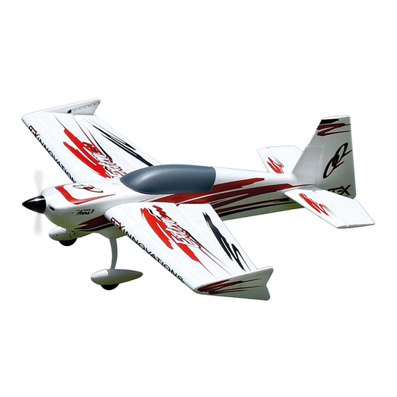
Pre-installed and custom-tuned Aura 8 Advanced Flight Control System with bounceback control The QQ Extra 300G2 is the evolution and accumulation of many years of design experience. A perfectly balanced airframe design combined Updated 1400kv motor and 50A ESC for more power with today’s most advanced control system gives an unmatched flying... -
Page 5: Specifications
BATTERY AND CHARGER MANUFACTURER. FAILURE TO COMPLY CAN RESULT IN FIRE. OPTIONAL ACCESSORIES The assembly of the QQ Extra 300G2 can be accomplished in less than one hour. Prior to assembling the airplane, it is FPZAU01 Potenza 3pc. Male-Male Servo Connectors... -
Page 6: Special Language Definitions
SPECIAL LANGUAGE DEFINITIONS The following terms are used throughout the product literature to indicate various levels of potential harm when operating this product: NOTICE: Procedures, which if not properly followed, create a possibility of physical property damage AND a little or no possibility of injury. CAUTION: Procedures, which if not properly followed, create the probability of physical property damage AND a possibility of serious injury. -
Page 7: Main Landing Gear Installation
MAIN LANDING GEAR INSTALLATION Required Tools and Fasteners: #1 Phillips Screwdriver (4) M3x10 Phillips Head Self-Tapping Screw Insert the landing gear assembly into the slot in the bottom of the fuselage. The landing gear will sweep forward as it moves away from the fuselage. -
Page 8: Optional Wheel Pant Removal
OPTIONAL WHEEL PANT REMOVAL For pilots that want the lightest possible setup, or for those that fly off of unimproved fields, the wheelpants on the QQ Extra 300G2 are removable. Two wheel collars have been provided in the hardware bag to retain the wheels after the wheelpants are removed. -
Page 9: Aura 8 Afcs
The Aura 8 Advanced Flight Control System (AFCS) installed in Works conveniently with all major radio systems your QQ Extra 300G2 is a giant leap forward in aircraft flight control system technology. Compatible with virtually every receiver on the Accepts signals from DSM Remote Receiver(s), Spektrum market today, the Aura features special configuration for DSM SRXL, Futaba S.Bus, Graupner Hott (Sum D of 8), JR... -
Page 10: Transmitter Setup
Make ONLY the changes shown in the Transmitter Configuration Guide unless otherwise noted. The Aura 8 in the QQ Extra 300G2 defaults to 3 flight modes that are switched via CH5/Gear in your transmitter. You may need to reassign CH5/Gear to a 3-position switch. -
Page 11: Connecting A Battery/Arming The Esc
CONNECTING A BATTERY TO THE LED CONTROLLER (NIGHT VERSION ONLY) The LEDs on your QQ Extra 300G2 are switchable via the transmitter, and are designed to be powered by 12 volts (3S Li-Po) through the 6S JST-XH balance tab on the LED controller. By default, the LED controller is plugged into Aura Port S7, which uses CH6/AUX1 from the transmitter for control. -
Page 12: Receiver Installation/Servo Connections
Jeti UDI12 (standard)* Graupner HOTT (Sum D of 8) QQ Extra 300G2 Wiki page at the below URL: A PPM (8CH, negative shift, approximately 22ms/frame) receiver may also be wiki.flexinnovations.com/wiki/QQExtra300G2 connected into Port 'B', however Aura will not auto-detect and setup must be performed through the Aura Config Tool (Windows Application). - Page 13 RECEIVER INSTALLATION/SERVO CONNECTIONS (CONTINUED) All Other Digital Receiver Connections While Spektrum and Futaba usually output their digital data stream, it may be necessary for JR DMSS, Graupner HOTT, and Jeti users to program the transmitter/receiver to output the correct digital format listed on the previous page. Consult your transmitter and receiver manuals for further details.
- Page 14 RX Channel Note: The LEDs on the QQ Extra 300G2 Night Version are able to be turned on and off via a channel from your transmitter. For PWM users, simply plug the servo lead from the LED controller into any open channel on your receiver (such as CH6/AUX1), and assign that channel to a 2-position switch on your transmitter accordingly.
-
Page 15: Horizontal Stabilizer Installation
HORIZONTAL STABILIZER INSTALLATION Required Tools and Fasteners: Clear Tape (4 Pieces, Included) Insert the horizontal stabilizer tube into the fuselage and roughly center. Slide the left and right stabilizer halves onto the tube. Ensure that the control horn orients towards the belly of the airplane and that the elevator joiner tabs are properly indexed. -
Page 16: Main Wing Installation
MAIN WING INSTALLATION Required Tools and Fasteners: #1 Phillips Screwdriver (2) M3x25 Self-Tapping Screws Invert the airplane so that the belly is facing up. Remove the belly hatch by pulling the exposed tab away from the fuselage. Install the wing tube into the fuselage. Slide the left or right wing panel on the wing tube and guide the servo wire and LED wire (night version only) into the fuselage. -
Page 17: Sfg Installation
SFG INSTALLATION Required Tools and Fasteners: Medium CA If you have a night version, remove the backing from the adhesive strip on the exposed LEDs in the wing tip. Place both LED strips on the side of the SFG that faces the fuselage, along the long edge of the SFG. One should be placed above the wing, and the other should be placed below the wing. -
Page 18: Battery Installation
BATTERY INSTALLATION Pull the spring loaded latch away from the nose, and lift the rear of the hatch off the fuselage. Install adhesived-backed hook and loop tape to both the battery and the battery tray. Place the battery in the battery tray and secure it with the provided hook and loop strap. Use the image below to reference the location of the recommended battery. -
Page 19: Transmitter Control Direction Test
TRANSMITTER CONTROL DIRECTION TEST Refer to the chart below to determine the proper control surface directions. If controls are reversed, DO NOT REVERSE CONTROLS IN THE TRANSMITTER OR THE AURA CONFIG TOOL. Email us at support@flexinnovations.com for corrective action. Note that BOTH the Transmitter Control Direction Test AND the Flight Controller Sensor Direction Test MUST BOTH BE PASSED! IF ONE DOES NOT PASS, DO NOT FLY! Proper Control Stick... -
Page 20: Aura 8 Sensor Direction Test
AURA SENSOR DIRECTION TEST Perform a test of the gyro system to verify the corrections made for a given movement are correct. If any of the tests do not result in the correct reaction for the airplane's gyro system, DO NOT FLY THE AIRPLANE, and contact us by email at support@flexinnovations.com or by phone at (866) 310-3539. -
Page 21: Propeller And Spinner Installation
PROPELLER AND SPINNER INSTALLATION Required Tools and Fasteners: M3x6 Phillips Head Screw (1) #1 Phillips Screwdriver M8 Nut 14mm or Adjustable Wrench M8 Prop Washer Insert the prop collet onto the motor shaft. Ensure that it is fully seated. Temporarily remove the prop nut and washer and install the propeller with the convex surface facing outward. The propeller size numbers are printed on the front face of the propeller and should orient forward. -
Page 22: Center Of Gravity
CENTER OF GRAVITY VERIFICATION The center of gravity (CG) location for the QQ Extra 300G2 is aligned with the front edge of the lower belly hatch. This location was determined from many test flights by designer and multi-time world aerobatic champion, Quique Somenzini. Lift the airplane from the underside of the wing to check CG. -
Page 23: Flying Your Qq Extra 300G2
A local AMA field Flight Mode 2 and trim for level flight. Land, adjust linkages and is the best location for flying your QQ Extra 300G2. If no AMA field return the trim to zero, and fly again. Repeat until the airplane flies is available in your area, a large open field with short grass and hands off, straight and level. -
Page 24: Airframe Repairs
AIRFRAME REPAIRS The QQ Extra 300G2 is molded from durable EPO foam and is repairable with most adhesives. Similar to building and repairing wood or composite aircraft, the correct glue for a given application is critical to the repair holding and not breaking again. For major repairs, such as a broken fuselage, epoxy is preferred because it allows time to correct any misalignment, and is less brittle than CAs. -
Page 25: Servicing The Power System
SERVICING THE POWER SYSTEM Required Tools and Fasteners: #1 Phillips Screwdriver M3 Hex Driver Following the installation instructions in reverse, remove the spinner, propeller and collet adapter from the motor. Use a #1 Phillips screwdriver to remove the cowling screws from the plastic tabs on the side of the fuselage. Pull the plastic tabs away from the fuselage, and remove the cowling from the fuselage. -
Page 26: Aircraft Troubleshooting Guide
AIRCRAFT TROUBLESHOOTING GUIDE Should you encounter any abnormal situations with your aircraft or it's installed electronics, refer to the matrix below to determine probable cause and a recommended solution for the action. If the required solution does not rectify the problem, please contact product support for further assistance. NOTICE Unless specifically required, ALWAYS troubleshoot the airplane with the propeller removed. -
Page 27: Limited Warranty
QQ Extra 300G2 Super PNP Green shall be that Flex will, at its option, either (i) service, or (ii) replace, QQ Extra 300G2 Night Super PNP Red any Product determined by Flex to be defective. Flex reserves the QQ Extra 300G2 Night Super PNP Green right to inspect any and all Product(s) involved in a warranty claim. -
Page 28: Ama Safety Code
Academy of Model Aeronautics National Model Aircraft Safety Code Effective January 1, 2018 GENERAL: A model aircraft is a non-human-carrying aircraft RC model aircraft must use the radio-control frequencies currently capable of sustained fight in the atmosphere. It may not exceed allowed by the Federal Communications Commission (FCC). - Page 29 . f l e x i n n o v a t i o n s . c o m ©2018 Flex Innovations, Inc. Premier Aircraft™, Potenza™, and Top Value RC™ are trademarks or registered trademarks of Flex Innovations, Inc. DSM®, DSM2™, and DSMX™ are trademarks or registered trademarks of Horizon Hobby LLC Futaba™...
Need help?
Do you have a question about the QQ EXTRA 300G2 and is the answer not in the manual?
Questions and answers