
Summary of Contents for O.L.E. (UK) T4020
- Page 1 O.L.E. (UK) Ltd T4020 \ T5020 \ INSTRUCTION & INSTALLATION MANUAL Revision: 02 Date: 26/03/2017 PD02/0002...
-
Page 2: Table Of Contents
Contents Introduction ............................2 Safety Warnings ..........................2 Contact Information.......................... 2 Principle of Operation ........................... 2 Installation Instructions ........................3 Mounting Holes ..........................3 Input Connections ..........................4 Output Connections .......................... 4 Power Input / Output Connections ....................5 Tank Level Probes ..........................5 Gauge Configuration ......................... -
Page 3: Introduction
Introduction The Purpose of this document is to outline the installation and operational procedures of the T4020 \ T5020. Safety Warnings To avoid injury please read this manual carefully before installation. Failure to do so could result in injury or failure of the equipment, this will invalidate any warranties given. -
Page 4: Installation Instructions
Installation Instructions Mounting Holes There are 4 mounting holes in the base of the unit (indicated with the Blue Circles). These are located behind the front panel screws. The distance between mounting holes is 110mm wide X 160mm high. Page 3 of 22... -
Page 5: Input Connections
Input Connections TP = Temperature Probe B8 or B2 = High Level probe or Level Probe Note: Jumper needs to be on Enable water bottom sensor for High Level and / or Bund Alarm B8 = Bund Probe Reed switch used in B8 and B2 probes: Rating 10w / Switching Voltage 0.5A 240VAC OUTPUT –... -
Page 6: Power Input / Output Connections
Power Input / Output Connections WARNING Before applying the power, DOUBLE CHECK all the connections to the inputs and outputs. 100 – 240v AC Power Pass Maximum through from Current - 0.7A Power Supply Tank Level Probes Standard Probes Legacy Probes Standard Probes Legacy Probes A12 / 3m = 3m Sensor with 10m of cable... -
Page 7: Gauge Configuration
The set-Up of the Tank Gauge system using Interface lead and he software on a PC / Laptop. Latest version of the software is V1.0.0.16 Tank Gauge adjustments can be made with the T4020 Configuration software. This needs to be loaded on to Service Laptop or an Office PC. - Page 8 (COM7), this will vary on whatever computer the programmer is attached. This is the figure that is entered in the T4020 Configuration Software. The communications lead RED LED should flash when you try to connect the USB programmer to show the address for the lead is correct.
- Page 9 This will open the Settings screen (Shown Below). Select from the drop down menu the Com Port number (as shown in the device manager) and click OK. Next step, click the Device tab at the top of the screen and click Connect. A pop up screen, Input Value will show, click on OK.
- Page 10 Click on the Display Options tab. Current Contrast Value, default is 47%. Set as required. Number of Significant figures is 5. On the T5020, there is the option to choose Resolution of Display, e.g. 50 Litres or 10 Litres etc. Set as required. 10.00 for instance. Display Units of Measure, set to Litres unless otherwise requested.
- Page 11 Click on the Tank Settings tab. Note: that the tank can be taller than the sensor range due to specific gravity. For example, the tank being 2.2m tall. If we say this is Diesel (DERV), then 2.2 x 0.835 = 1.837 affective range on the sensor.
- Page 12 Next step is to Access the T5020 additional settings and Summary Screen, press the Ctrl, and letter H keys simultaneously, and click on Device Status Tab. This will bring up the summary screen of what has been programmed into the unit as shown above The Summary page.
-
Page 13: Operational Instructions
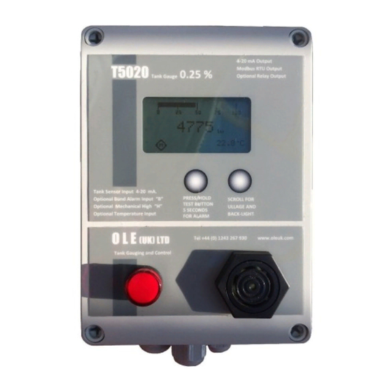
Operational Instructions Alarm Mute Visual Display Button Scroll Button for Ullage and Backlight LED Light Audible Alarm Temperature Probe Input 4-20 mA Output High Input Probe Input Bund Input RS485 Connector Power Input / Output Alarm Outputs M, 1, 2, 3 Page 12 of 22... -
Page 14: Appendix 1 (T5020 Wiring Diagram)
Appendix 1 (T5020 Wiring Diagram) Page 13 of 22... -
Page 15: Appendix 2 (Modbus Register Table)
Appendix 2 (Modbus Register Table) Page 14 of 22... - Page 16 Page 15 of 22...
- Page 17 Page 16 of 22...
- Page 18 Page 17 of 22...
-
Page 19: Appendix 3 (Accessories)
Appendix 3 (Accessories) B8 – Bund Probe / Level Switch The Bund Probe has an integral N/C (Normally Closed) level switch. The Sensor body is made from 304 Stainless Steel and the cap is 316 Stainless Steel. The float is NBR (Nitrile) which is good in Oil, Diesel, Petrol, most spirits and water based products (SG: 0.7 to 1.5). -
Page 20: Tp - Temperature Sensor
TP – Temperature Sensor The temperature sensor is a thermistor housed in a 316 Stainless Steel body. The standard cable is Polyurethane sheathed and 10.0m in length and supplied with a 1” fitting. °C to 70°C. It measures the temperature of the fluid in the tank from 0 Not suitable for ATEX applications. -
Page 21: Usb Programmer And Configuration Software
USB Programmer and Configuration Software This kit allows the user to connect to the T5020 Gauge using a laptop or a desktop PC. The free configuration software enables the user to set the Tank Shape / Size, Specific Gravity of the product, RS485 NODE ID, Sensor Parameters, Alarm Trigger percentages and direction. -
Page 22: F. A. Q's / Troubleshooting
Siren will not sound when the test button is pressed. On T4020 / T5020 the test button must be pressed for 5 seconds before the siren will sound. Check the 8-way green connector is fitted correctly (see wiring diagram). When R5 relays are incorporated the siren, connection is on the front 8-way green connector. - Page 23 Damage to the input circuitry can make the gauge read low by 5% and 10%. Check the board for a burning smell. The board is usually beyond economical repair and suggest purchasing a new board, Part No. T4020-0002B. • Bund Alarm Connection Bund alarm is connected but does not operate.
Need help?
Do you have a question about the T4020 and is the answer not in the manual?
Questions and answers